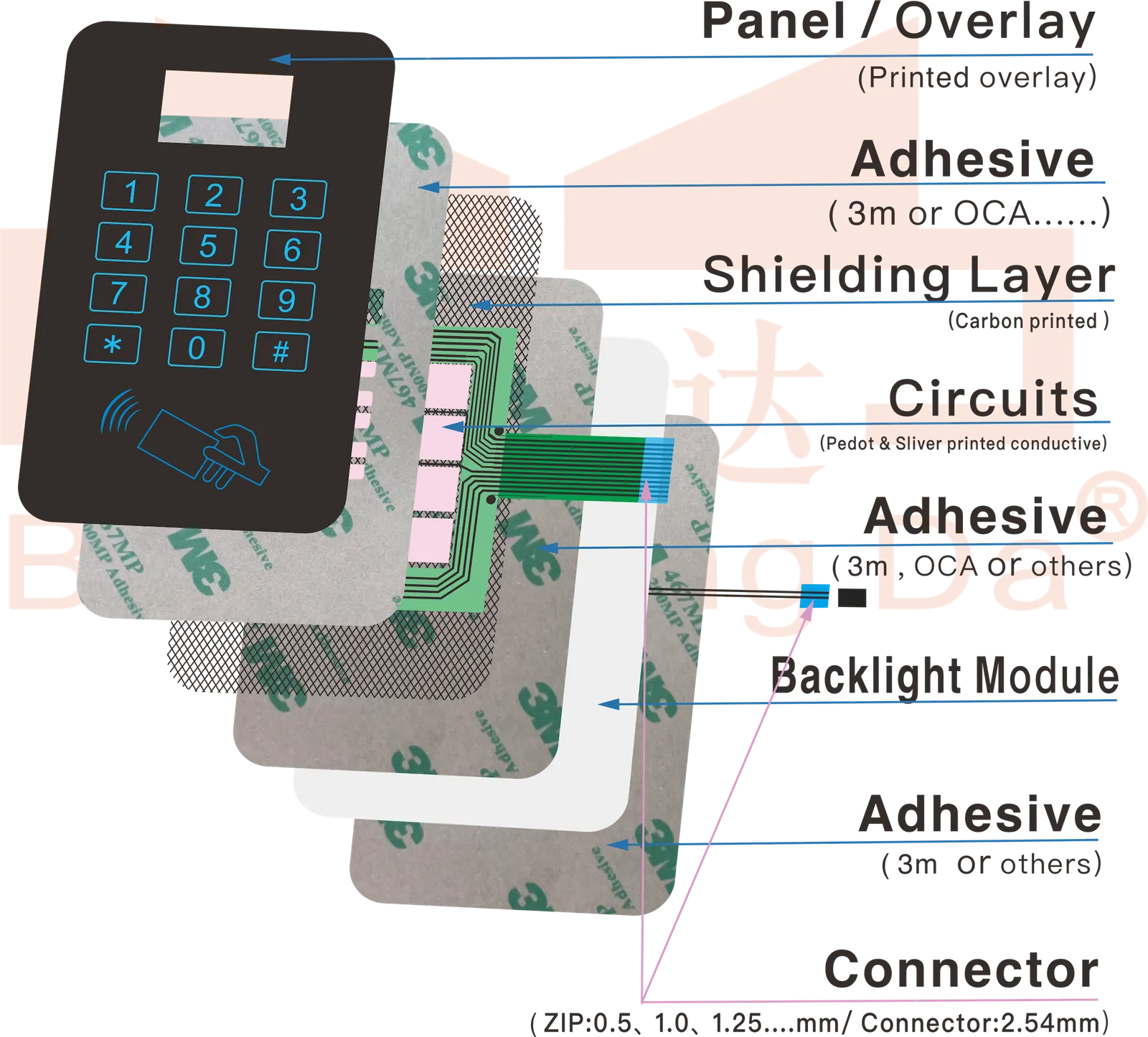
Choose an FPC membrane switch when the interface needs dense copper routing, controlled contact fingers for a defined connector, or a compact tail path that cannot be handled cleanly by a simpler printed-silver circuit.
What Is an FPC Membrane Switch?
An FPC membrane switch uses a flexible printed circuit as the electrical layer beneath the graphic overlay and key structure. The FPC can carry narrow traces and terminate in plated contact fingers, solder pads or another specified interface.
FPC is not automatically the best choice for every keypad. A simple, static key matrix with generous routing space may be more economical as a printed-silver membrane circuit. The decision should follow circuit density, connector geometry, tail duty, enclosure clearance and the evidence required at sample approval.
FPC Membrane Switch Structure
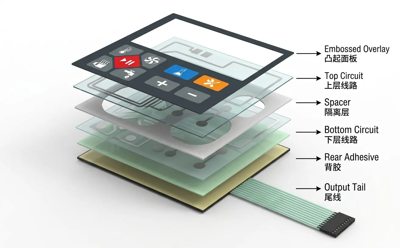
Graphic OverlayPET, PC or customized film with printed icons, windows, logo, texture and optional embossing.
Adhesive LayerBonding layer selected according to the housing material, surface condition and assembly method.
Spacer LayerCreates the switch gap and helps control key travel, tactile response and circuit separation.
Metal DomeOptional tactile structure for clear key feedback when the application requires click feel.
FPC Circuit LayerFlexible printed circuit layer for dense routing, compact tail paths and stable electrical connection.
Reinforcement LayerStiffener or reinforcement can be added near the connector, tail exit or bend-risk area.
Connector TailZIF, solder, pin or customized tail connection can be reviewed according to the PCB interface.
ZIF Connector, Stiffener and Bend Radius Checks
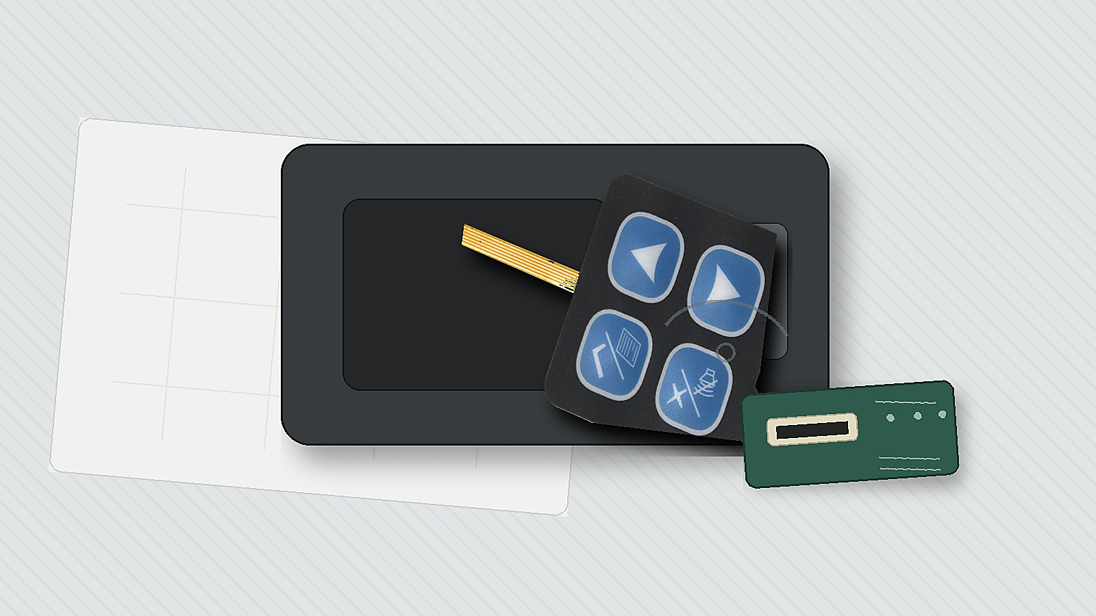
Check the connector and the first bend after the panel as well as the visible key area. Review these details before tooling and sample approval.
DecisionWhat to confirm before sampling
ZIF pitch and contact sideConnector model, pin count, top or bottom contact, PCB orientation and insertion depth.
Stiffener length and thicknessMatch the connector datasheet and leave enough rigid support without pushing the bend point into the housing wall.
Tail exit directionConfirm whether the tail leaves from the top, side or rear of the overlay and whether the enclosure has a clean slot or radius.
Bend radius riskAvoid a sharp fold at the adhesive edge, stiffener end or connector entrance. Check the assembled sample in the real housing.
Service accessDecide whether the operator can insert and lock the tail after the panel is bonded, especially in compact instruments.
A loose sample can mate correctly on a bench and still fail after bonding if the stiffener collides with the housing wall, the connector lock is inaccessible or the first bend starts at the contact area. Approve the tail only after a mounted insertion and removal check.
For a connector-fit review, use the ZIF tail contact-exposure checklist. For the housing route, use the mounted-tail bend approval guide.
Configuration Options to Define
Design inputWhat the drawing or RFQ should define
Circuit and keysMatrix or individual circuits, trace constraints, tactile or non-tactile keys, dome type and any LEDs.
Overlay and windowsPET or PC film, finish, legends, display windows, embossing and adhesive-free areas.
Tail terminationZIF contact pitch and side, exposed finger length, solder pads, pin interface or buyer-specified connector.
StiffenerMaterial, thickness, length and location matched to the mating connector and housing clearance.
Tail dutyStatic installation, one-time service bend or repeated movement. Dynamic flex needs its own radius, cycle and strain-relief validation.
Lighting and sealingLED or LGF zones, light blocking, adhesive border, tail-exit protection and assembled enclosure responsibility.
Acceptance evidenceContinuity and pin-map check, connector fit, mounted tail route, key operation and any buyer-defined environmental test.
Dimensions, materials and acceptance limits remain project specific. They should be released from the buyer's controlled drawing and the approved mounted sample, not from a generic product-page value.
FPC or Printed-Silver Circuit?

Buyer conditionPractical direction
Dense traces or a defined ZIF interfaceReview an FPC circuit with controlled contact fingers, stiffener geometry and insertion evidence.
Simple static key matrix with generous spaceA printed-silver membrane circuit may meet the need without adding FPC complexity.
Tail bends once during assemblyEither route may work; approve the actual exit radius, strain relief and service access in the housing.
Tail moves repeatedly in useDo not assume a standard keypad tail is a dynamic-flex cable. Define movement, radius and cycle validation separately.
Harsh cleaning, moisture or outdoor exposureThe FPC circuit alone does not create a sealed product. Review overlay edges, adhesive land, tail exit and enclosure sealing together.
Failure Modes to Review on the Mounted Sample
Contact fingers do not seat
Pitch, contact side, exposed length or stiffener thickness does not match the connector.
Tail creases at the exit
The housing slot or adhesive edge forces the first bend too close to the circuit or stiffener.
Pin map reverses
Drawing view, keypad orientation and PCB connector numbering are not controlled from the same datum.
Keys change after bonding
Housing steps, adhesive compression or unsupported domes alter travel and tactile response.
Service access is blocked
The panel can be installed, but the connector lock cannot be reached without pulling or twisting the tail.
Moisture reaches the tail path
A sealed front surface is undermined by an exposed tail exit, connector area or enclosure water path.
Where the FPC Structure Fits
The product fit comes from the interface geometry, not the industry label. These application examples still require the buyer to own system-level safety, software, connector and enclosure validation.
Robot and AMR Service Panels
Compact maintenance keys where the full tail must route around batteries, frames or service covers without entering a pinch point.
Home-Use Medical Controls
Low-profile keys and status windows that must remain understandable, cleanable and serviceable for patients, caregivers or technicians.
Industrial Controllers
Dense keypad functions, defined connector access and a repeatable tail route inside a limited control enclosure.
Handheld Instruments
Portable meters and service tools where the tail must clear internal supports and reach a small PCB.
Automotive Component Interfaces
Buyer-defined interior control modules where the FPC keypad is one component and vehicle-level qualification remains with the OEM or Tier 1.
Communication Equipment
Status and navigation keypads that need controlled tail pins, indicator windows and service access to the mating electronics.
Customization Options
Circuit and Tail Design
- FPC circuit routing optimization
- Tail length, width and exit direction
- Stiffener and reinforcement design
- Shielding or ground line planning where required
Connector Interface
- ZIF connector tail
- Solder pad or pin connection
- Custom pitch and pin count
- Contact direction and mating PCB review
Lighting and Sealing
- LED or LGF backlight integration
- Waterproof sealing design
- Light-blocking and window structures
- EMI shielding options based on requirements
Overlay and Appearance
- PET or PC graphic overlays
- Surface texture, color and icon printing
- Embossed or flat key areas
- Integration with PCB or hybrid systems
Mounted-Sample Evidence Before Release
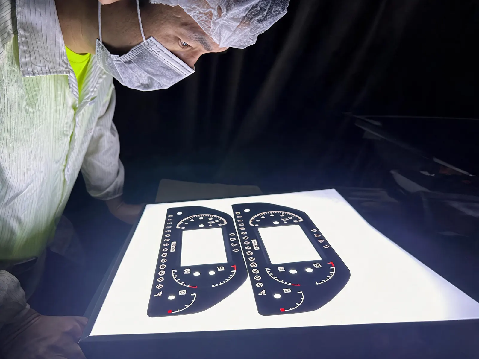
Agree on the evidence package before samples are built. The useful record connects the approved drawing to the actual connector, enclosure and keypad function.
- Released pin map and drawing revision
- Continuity result for the approved circuit
- Close photo of contact fingers and stiffener
- Connector insertion and lock-access check
- Mounted tail route and first-bend clearance
- Key operation after the panel is bonded
- Window, legend and overlay alignment
- Adhesive contact around cutouts and edges
- Buyer-defined cleaning or environmental checks
- Recorded deviation and resample decision when needed
A flat bench test does not prove mounted performance. Release the structure only after the sample is assembled in the intended housing or a representative fixture.
Design Information Needed for Quotation
Start your FPC keypad quotation with the panel drawing or sample photos, mating connector details, housing route and sample or production quantity. Include the other available information below so the circuit and mounted tail can be reviewed together.
- 2D drawing, 3D file, artwork or old sample photos
- Panel size, key layout, window areas and overlay material requirement
- Electrical function, circuit layout, pin count and connector type
- Tail exit location, tail length, bend direction and housing route
- Tactile or non-tactile key requirement
- Backlight, waterproof, EMI shielding or special reliability requirement
- Application environment and expected assembly method
- Prototype quantity, production quantity and target lead time
- ZIF connector model or datasheet, including pitch, contact side and lock type
- Stiffener thickness, exposed finger length and connector insertion direction
- Housing slot, available bend radius and any repeated-movement requirement
- Photos or notes showing how the tail will reach the PCB after the overlay is bonded
- Static-install, service-bend or repeated-movement duty for the tail
- Required sample evidence and acceptance limits for connector fit, key feel and enclosure assembly
If the connector is not fixed yet, include the available PCB space and any connector options under consideration.
Send FPC Drawings for Review
Download FPC Membrane Switch Brochure
Request an overview of Baoshengda's custom FPC membrane switch structure, flexible printed circuit options, connector tail design, backlight support, quality checks and quotation requirements.
Request Product Brochure
FAQ
What should buyers confirm before choosing a ZIF connector tail?
Confirm connector pitch, contact side, pin count, insertion depth, stiffener thickness, PCB orientation and the space available for assembly or service access.
How should bend radius be reviewed on an FPC membrane switch?
The tail should not be folded sharply at the panel edge or stiffener. Review the housing exit, bend direction, fixture radius, repeated movement risk and whether the first sample can be assembled into the real enclosure.
When is FPC a better fit than a printed-silver membrane circuit?
FPC is useful when the design needs dense copper routing, controlled contact fingers or a defined ZIF interface. A simple static key matrix with generous routing space may still be a better fit for a printed-silver circuit.
Can an FPC membrane switch be backlit or sealed?
Yes. LED or LGF backlighting and sealing structures can be reviewed, but the result depends on circuit layout, light area, adhesive border, tail exit, housing fit and total stack thickness.
What files help quote an FPC membrane switch quickly?
Send 2D drawings or 3D housing files, artwork, circuit or pinout, connector model, tail route, bend area, overlay material, environment, sample quantity and production quantity.
Related FPC and Connector Buyer Guides
These recent engineering notes support the same RFQ decisions and should be reviewed with the drawing package.
Part of Baoshengda HMI system ecosystem
FPC membrane switches are the compact circuit and input layer inside Baoshengda HMI system solutions. They are useful when the interface needs tighter routing, connector reliability or thin assembly space.
Need a custom FPC membrane switch for your project?
Send your drawing, connector model, tail route and housing notes. Baoshengda can review whether the ZIF tail, stiffener, bend radius and overlay stack are ready for sampling.