
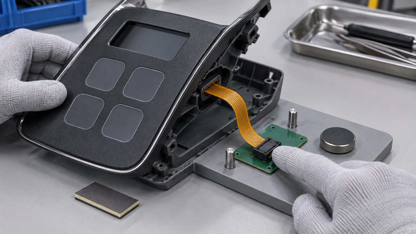
Decide the supplier boundary before asking for price. In an automotive smart-surface HMI, the decorative trim, sensing layer, printed circuit, flexible tail, connector, haptic actuator, lighting electronics and firmware may belong to different companies. The RFQ should identify who owns each layer, then freeze one tail-exit datum, connector-side pin map, contact side, mating part and first-bend keepout. Without that handoff, two quotations can describe different products, and a surface sample that looks correct may be electrically impossible to integrate. Approve the flexible interface, bench connection and mounted trim in separate stages.
Current smart-surface development makes ownership visible
An Antolin and UltraSense announcement dated September 8, 2026 describes a collaborative automotive interface program that combines touch and force sensing with visual and haptic feedback. The announcement assigns advanced electronics, sensing architecture, firmware and algorithms to one participant, while integration, engineering and industrialization sit with another.
That public announcement does not say the platform uses a Baoshengda component, a membrane switch or the specific flex construction discussed here. Its useful sourcing signal is the explicit split of responsibilities. A smart surface may look like one part to the driver while remaining a stack of products, drawings and acceptance owners behind the trim.
For a buyer considering a separate flexible printed interface, the quotation question is not simply, “Can you make this shape?” It is, “Which layer and connection does each supplier release, and what evidence proves that the handoff works before the trim is frozen?”
Start with an owner matrix, not the visible artwork
List every layer from the touched surface to the controller. A typical project may include decorative film or molded trim, adhesive, light mask, sensing electrodes, spacer or support, printed circuit, flexible tail, stiffener, connector, board, haptic actuator and housing. Not every project uses every layer, and several layers may be combined. The RFQ should show the actual intended stack rather than asking suppliers to infer it from a rendering.
Assign one owner to each released output. The trim owner may control surface grain, color, thickness and openings. The flexible-interface supplier may control printed conductors, switch or sensing zones, tail geometry, stiffener and specified termination. The electronics owner controls supply, input circuit, scanning and signal processing. The haptic owner controls actuator selection and drive. The system integrator controls the assembled load path, software behavior and vehicle acceptance.
If two companies both assume the other owns the connector pinout, the risk appears late. If both include it, quotations may contain duplicate scope. If neither owns the adhesive landing or tail corridor, a good loose sample can become impossible to install.
Freeze one physical and electrical handoff
A useful RFQ has one controlled view that connects the visible surface to the controller-side interface. Use stable datums for the surface outline, active zones, tail exit and connector orientation. Then relate the pin map to that same view.
| RFQ decision | Buyer evidence to send | Flexible-interface supplier output | Keep with the system owner |
|---|---|---|---|
| Layer boundary | Section view with every layer and named owner | Quoted film, circuit, adhesive, tail and termination scope | Trim architecture and complete stack release |
| Tail exit | Datum from panel or trim, exit direction and corridor | Tail outline, conductor route and first-bend keepout | Housing clearance, assembly motion and service access |
| Connector | Connector-side view, contact side, pitch, mating part and latch direction | Defined contacts, stiffener and specified connector assembly | Controller receptacle placement and harness ownership |
| Pin map | Stable signal names and pin-one reference | Continuity matrix from active zone to termination | Supply, scanning, filtering and software action |
| Haptic interface | Actuator position, support and allowed vibration path | Clearances and isolation features included in the flexible part | Actuator drive, tuning, noise and vehicle-level feel |
| Sample evidence | Fixture, test points, acceptance owner and revision | Dimensional, continuity and agreed component checks | Integrated response, fault handling and vehicle validation |
Do not dimension the tail only by total length. Control its centerline at the exit, first straight section, minimum bend zone, stiffener start, exposed-contact length and connector insertion direction. A longer tail can still fail if its stiffener enters the bend, the contacts face the wrong side or the latch is blocked after assembly.
Use a connector-side pin table rather than a circuit sketch that can be viewed from either side. Mark whether the drawing shows the contact face, component face or cable-entry side. Freeze the mating connector manufacturer and part definition only when the program has actually selected it. Otherwise quote clearly separated options.
Keep sensing and haptic evidence separate from flex continuity
A flexible printed circuit can provide a controlled connection path, but continuity does not prove the complete smart-surface experience. A key or sensor zone may connect correctly while the assembled trim attenuates touch, distributes force across adjacent zones or changes the haptic response. A haptic actuator can operate while the flex is strained at its tail exit.
Give each evidence layer a different question. Component evidence asks whether dimensions, conductors, contacts, tail and termination match the released drawing. Bench integration asks whether the board reads the intended channels through the final connector and whether the actuator can operate without rubbing or pulling the flex. Mounted-trim evidence asks whether the full stack supports the intended touch, force, lighting and haptic behavior under the actual support conditions.
The flexible-interface supplier can support an agreed continuity matrix and, when the buyer provides the fixture and circuit, comparative response checks. It should not be asked to certify an algorithm, a complete haptic feel, functional safety or driver-distraction performance from a loose film sample.
Approve three stages with different acceptance owners
Stage 1, flexible interface: Inspect the outline, active zones, layer registration, adhesive geometry, tail exit, first-bend keepout, stiffener, exposed contacts or connector and point-to-point continuity. Record the drawing, artwork, circuit and termination revisions. This stage catches mirror images, shifted exits and incorrect contact sides before the complete trim is involved.
Stage 2, bench handoff: Mate the final connector to a representative controller board or approved test fixture. Verify every channel at the connector-side pin reference. Route the tail through the planned bend and strain-relief condition. Place the haptic actuator in its intended support location, but keep its drive and performance acceptance under the electronics and system owners. Repeat continuity while the actuator is operated only if the test is controlled and safe.
Stage 3, mounted trim: Install the complete surface stack in representative housing hardware. Check surface registration, display opening, support under each active zone, tail clearance, connector access and removal direction. Then the system team evaluates touch, force, lighting, haptic response, software state and vehicle requirements. A Stage 1 pass cannot substitute for this release.
When a stage fails, record the failed boundary. “HMI failed” is too broad. A pin-map reversal, tail interference, unsupported zone, actuator contact and software mapping error need different owners and corrective actions.
What an FPC membrane-interface supplier can support
A supplier of a custom FPC membrane switch and flexible interface with a controlled tail and connector can review buyer-supplied layer drawings, active-zone geometry, printed conductors, adhesive openings, tail exit, stiffener, contact side and specified termination. It can manufacture the agreed flexible portion and provide dimensional, appearance, continuity and connector evidence defined in the quotation. When representative trim or a fixture is supplied, it can also support a controlled mounted-fit review.
The component supplier does not automatically own the decorative trim, touch or force algorithm, haptic actuator, lighting electronics, firmware, controller design, electromagnetic compatibility, functional safety, driver interaction or complete vehicle approval. Those items require the responsible system teams, applicable requirements and separate validation. The public smart-surface announcement is market context, not evidence that a proposed component architecture has been selected or approved.
This boundary should be visible in the quotation. It makes supplier comparisons fair and prevents a component sample from being presented as proof of a complete automotive HMI.
Drawing, sample and RFQ checklist
Before using the Request Quote page, prepare one controlled package:
- front-surface and section drawings with the decorative, sensing, circuit, adhesive, support and housing layers identified;
- a layer-and-owner matrix showing what the buyer, trim supplier, flexible-interface supplier, electronics supplier, haptic supplier and integrator release;
- active-zone IDs tied to the connector-side pin map and controller signal names;
- panel datum, tail-exit datum, route corridor, first-bend keepout, stiffener limits and assembly direction;
- contact side, pitch, exposed-contact geometry or connector, mating part, latch direction and pin-one reference;
- voltage, readout or scanning boundary needed for sample checks, without asking the film supplier to infer system electronics;
- haptic actuator position, mechanical support, clearance and the owner of drive and tuning evidence;
- Stage 1 component, Stage 2 bench-handoff and Stage 3 mounted-trim acceptance methods;
- approved revisions, prototype and production quantities, required inspection records and change-control rules.
A quotation built from this package can show exactly what is included, which assumptions remain open and which evidence belongs to the final system. That is more useful than comparing nominal unit prices for supplier scopes that are not actually the same.
Need help reviewing a structure?
Send your drawing, photos, application, and quantity. Baoshengda can help check the structure before sampling.
Send Drawing for Quote