
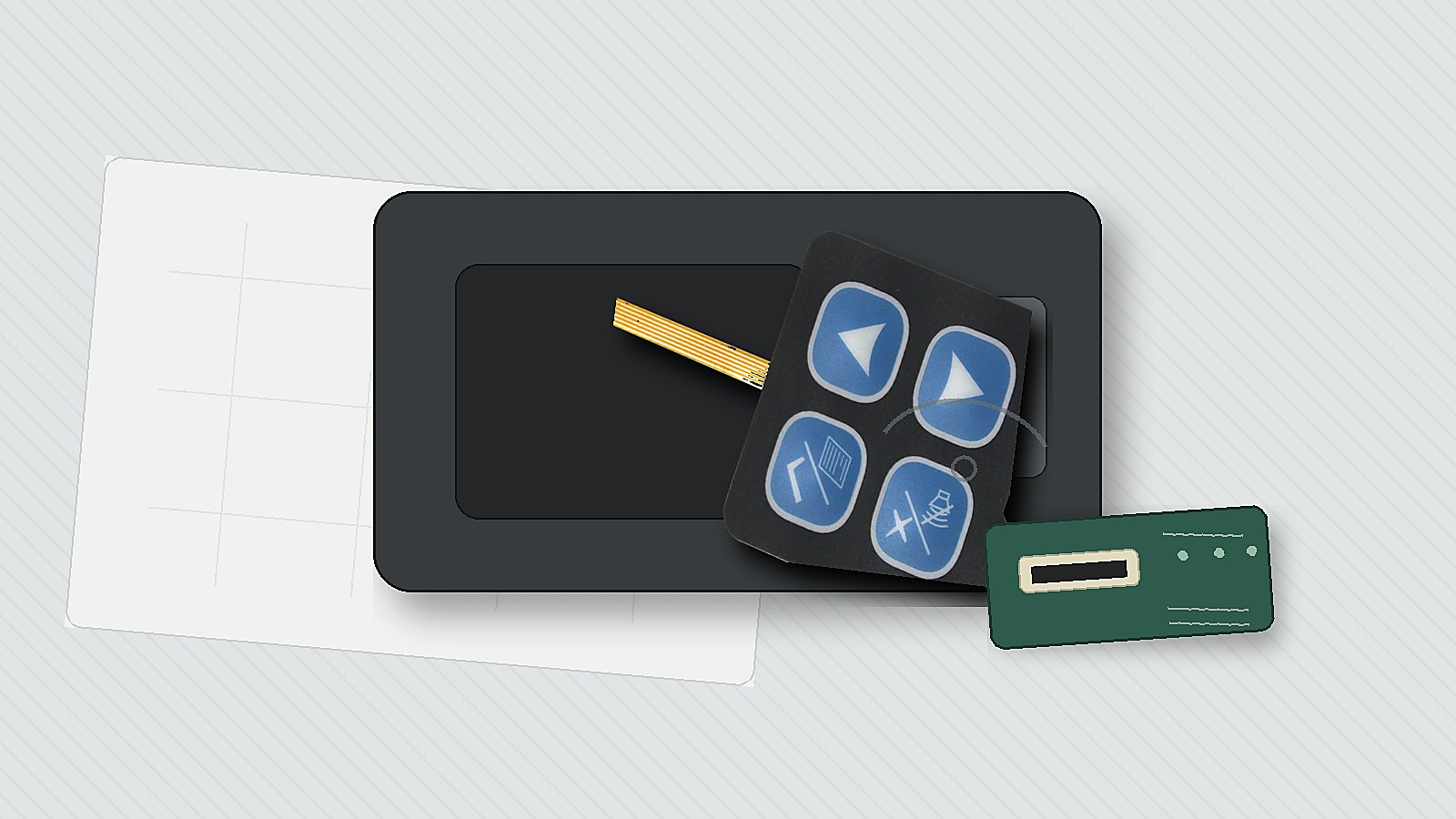
Quick answer: approve an FPC membrane switch sample only after the tail route, bend radius, stiffener, ZIF connector fit, and housing exit are checked together. The keypad can click correctly on the bench while the flexible circuit tail is stressed after installation. If your project uses a thin keypad with an integrated flexible tail, Baoshengda's FPC membrane switch page is the closest product reference.
An FPC keypad can pass a flat electrical check and still fail after installation. The critical question is whether the tail, stiffener, connector, and housing route work together without forcing a sharp bend or partial ZIF engagement.
What should a buyer confirm before the FPC outline is frozen?
Start from the final device, not from the flat keypad drawing. The FPC tail must leave the switch area, pass through the housing, and reach the PCB connector without rubbing a sharp edge or folding too close to the keypad body.
Before quotation, confirm these points:
- Keypad outline, active key area, and visible overlay window.
- Tail exit position relative to ribs, screws, clips, and sealing foam.
- Whether the tail folds once, twice, or stays nearly flat after assembly.
- Connector type, pitch, contact side, insertion direction, and locking style.
- Required stiffener length and thickness at the connector end.
A common failure mode is a tail that looks long enough on the drawing but becomes short after the housing route is added. That can pull the ZIF end during assembly or leave the tail bent against a plastic wall.
How should bend radius be reviewed?
Do not approve an FPC tail by saying only that it is flexible. Ask where it bends, how often it bends, and whether the bend stays in one place after the product is closed.
Use this review method:
- Mark every bend point on the assembly drawing or housing photo.
- Keep the first bend away from the keypad edge and contact area where possible.
- Avoid a sharp fold directly beside the stiffener.
- Check whether adhesive, foam, or a bracket fixes the tail in a safe path.
- Ask for a mounted sample photo if the housing is already available.
The tradeoff is space. A larger bend path is safer for the tail, but it may require a longer slot, a different connector position, or a small route channel inside the housing.
What makes the ZIF connector area risky?
The ZIF connector is a small detail, but it can block assembly if the contact side, stiffener, or insertion direction is wrong. Buyers should not wait until the first sample arrives to check this.
Confirm these connector details with the PCB team:
- Connector pitch and available insertion depth.
- Contact side up or contact side down.
- Tail thickness including copper, coverlay, adhesive, and stiffener.
- Stiffener color and length if visual inspection is needed.
- Pull direction after the keypad is mounted.
If the connector latch is close to a housing wall, the operator may not have enough finger or tool space to close it. That issue is easier to fix before the tail length and exit angle are locked.
What should be tested on the first sample?
The first sample should prove more than key feel. It should show whether the electrical and mechanical route can survive normal assembly handling.
Ask for or run these checks:
- Fit the switch into the actual enclosure or a close fixture.
- Insert and lock the FPC tail into the planned ZIF connector.
- Press each key while the tail is routed in the installed position.
- Check for intermittent output when the tail is moved within the allowed route.
- Inspect whether the overlay, spacer, and tail exit stay flat after mounting.
For sealed or outdoor devices, review the tail exit together with gasket position and adhesive landing. A good electrical sample can still fail if the route opens a leakage path or lifts the front seal.
What files should be sent for an RFQ?
A useful RFQ package reduces guessing. Send enough information for the factory to judge the switch surface and the tail route at the same time.
Include these items when you request a quote:
- 2D drawing with keypad outline, tail length, tail width, and connector end details.
- Overlay artwork or key layout with color and window requirements.
- PCB connector model or pitch, plus contact-side direction.
- Housing photo, slot position, route path, and any nearby ribs or screws.
- Expected operating environment, cleaning method, and sealing requirement if any.
- Sample approval notes for key feel, circuit continuity, and mounted fit.
If the connector is not chosen yet, say that clearly. The design can still move forward, but the quotation should leave the connector end and stiffener details open until the PCB side is confirmed.
When should the design be changed before tooling?
Change the design before tooling if the sample review shows tail stress, connector access problems, or a route that depends on forcing the FPC into place. Small changes at this stage are usually easier than accepting an unstable assembly.
Typical changes include moving the tail exit, increasing tail length, changing contact side, adding a stiffener, changing connector position, or adding a housing guide feature. The right decision depends on the enclosure, PCB location, and assembly process, not only the switch drawing.
For Baoshengda, the fastest next step is a drawing plus housing route review. That gives the engineering team enough context to recommend the FPC tail, connector end, overlay stack, and sample checks before the first production-style keypad is made.
Need help reviewing a structure?
Send your drawing, photos, application, and quantity. Baoshengda can help check the structure before sampling.
Send Drawing for Quote