
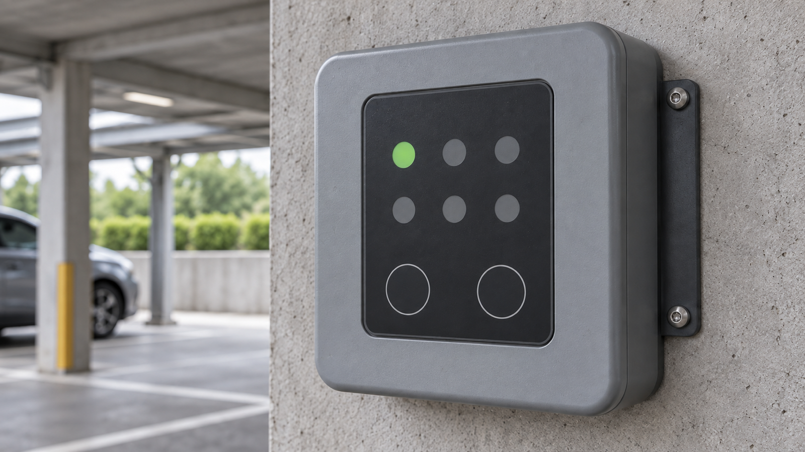
A membrane status panel for a wireless charger should keep each illuminated state visually separate from its neighbours. Start with the lighting zones and the opaque material between them, not with a brighter LED. If light from one zone makes another look active, an attractive all-on sample can hide the problem. Ask to review one indicator at a time in the intended housing, under both dim and bright ambient light. You can begin the discussion with a marked panel image and a list of states; a complete production drawing is not needed to identify the first design questions.
A charging state needs its own visible boundary
A small status window is useful only if the viewer can distinguish its active and inactive appearances. On a local charger panel, an OEM might allocate separate windows to availability, positioning or an interruption. Those meanings are examples, not a universal charging-state convention. The equipment team must define the actual messages and how they relate to its software and other displays.
Optical crosstalk means light intended for one visible area reaches another. It is different from an unwanted electrical signal: both can make a neighbouring indicator appear active, but they require different fixes. A component review should therefore separate where the light travels from which LED the controller actually drives. Changing printed colours alone does not establish that separation.
A membrane construction can combine flat key areas and selective indicator windows in one front face. That does not require the entire face to share one illuminated cavity. Where independent states matter, the light path deserves as much attention as the visible artwork.
Wireless charging adds a positioning state, not a membrane specification
Electreon's September 14, 2026 announcement of Lite DOT describes a stationary wireless charging arrangement for passenger cars and light commercial vehicles, with a ground pad, wall unit and vehicle receiver. Its introduction at IAA Transportation puts vehicle positioning and charging feedback into a concrete equipment discussion rather than a general prediction about future interfaces.
The manufacturer's product page explains that charging status is available through the vehicle display or its app. It also states that the recently introduced product is not yet commercially available. Neither page specifies the membrane construction discussed here. This article is not a description of that manufacturer's control panel or a claim to supply it.
The relevant component decision arises when another OEM chooses to provide a local membrane status face alongside its other feedback channels. Removing a plug-in action does not remove the need to communicate equipment state clearly. The chosen indication architecture still needs its own component review.
Choose where the light may travel
A light guide film distributes light from an LED across a selected area. CSI Keyboards' light-guide explanation describes films beneath the graphic overlay and notes that multiple films can illuminate separate graphic features. That is a useful design option, not evidence that any particular panel will meet an optical requirement without samples.
Compare the intended illuminated areas before selecting a stack:
| Lighting arrangement | Useful starting point | Tradeoff to resolve |
|---|---|---|
| Local LED behind a small window | A compact, independently indicated state | LED position and available depth can create a bright spot rather than an even window |
| Separate guided-light zones | A larger legend or several features that must operate independently | Zone boundaries, light-source placement and assembly registration need coordinated drawings |
| A common illuminated field | Several legends that intentionally illuminate together | It is not automatically suitable for independently meaningful adjacent states |
| Opaque mask or physical light barrier | Blocking an unwanted path between zones | Its position must remain effective in the assembled thickness and tolerance stack |
The appropriate choice depends on the visible area, available depth and which zones must light independently. A larger gap may simplify optical separation but consume panel space. A tighter layout may require a more carefully controlled mask or barrier. Increasing brightness can improve the active window while making leakage more obvious, so it is not a substitute for reviewing the path.
For a backlit membrane switch with selective lighting zones, send the intended face layout together with the housing recess and the proposed light-source arrangement. If the LEDs are on the equipment PCB rather than supplied within the panel, identify that boundary explicitly. It changes which supplier can adjust alignment and spacing.
Read the dark windows as carefully as the lit one
Review a representative mounted sample, not only a loose face under a camera. Start with all indicators off to identify reflections and the inactive appearance. Then drive each intended zone separately while checking its neighbours. Finally inspect combinations that the equipment can actually display. A photograph with every window illuminated cannot show whether one zone contaminates another.
Keep the supply condition, dimming setting, housing, viewing distance and ambient light recorded for the comparison. Agree acceptance criteria before interpreting photographs; camera exposure is not a luminance measurement. Where quantitative contrast or uniformity matters, the equipment team should specify the measurement method and limits rather than asking the panel supplier to invent them.
If a neighbour appears lit, confirm the drive state first. When the unwanted appearance persists with that zone unpowered, investigate reflections, guide boundaries, masking and gaps in the mounted assembly. This sequence avoids trying to solve an electrical problem with artwork or an optical problem with firmware.
Bring the panel layout and the state list together
An initial enquiry can start with a photograph, sketch or incomplete layout. Mark which areas should illuminate independently, describe where the unit will be viewed, and explain the ambiguity you want to prevent. Baoshengda can review the component lighting zones, overlay windows, light-blocking approach and connection requirements within its proposed supply scope. A first discussion establishes missing information, not an unconditional promise of manufacturability.
Use a short handoff that becomes more precise as the project develops:
- To start: share the visible layout, intended states, available housing space and any confusing sample appearance.
- For an indicative quotation: identify quantities, the proposed optical stack, who supplies the LEDs and driver, connection assumptions and any unresolved alternatives.
- For sample review: provide the representative mounting parts, operating conditions, one-zone-at-a-time sequence and agreed visual or measured acceptance criteria.
- For production release: approve the construction and artwork revisions, lighting-zone definitions, inspection method and the accepted sample reference.
The component supplier does not determine charging-state logic, vehicle compatibility, charger safety or the equipment's environmental approval. Those remain system decisions. If your current information is only a front-panel sketch, request a component review and quotation discussion with the zones marked. The useful first outcome is agreement on what each light must show, what must stay dark, and which sample will resolve the remaining uncertainty.
Need help reviewing a structure?
Send your drawing, photos, application, and quantity. Baoshengda can help check the structure before sampling.
Send Drawing for Quote