
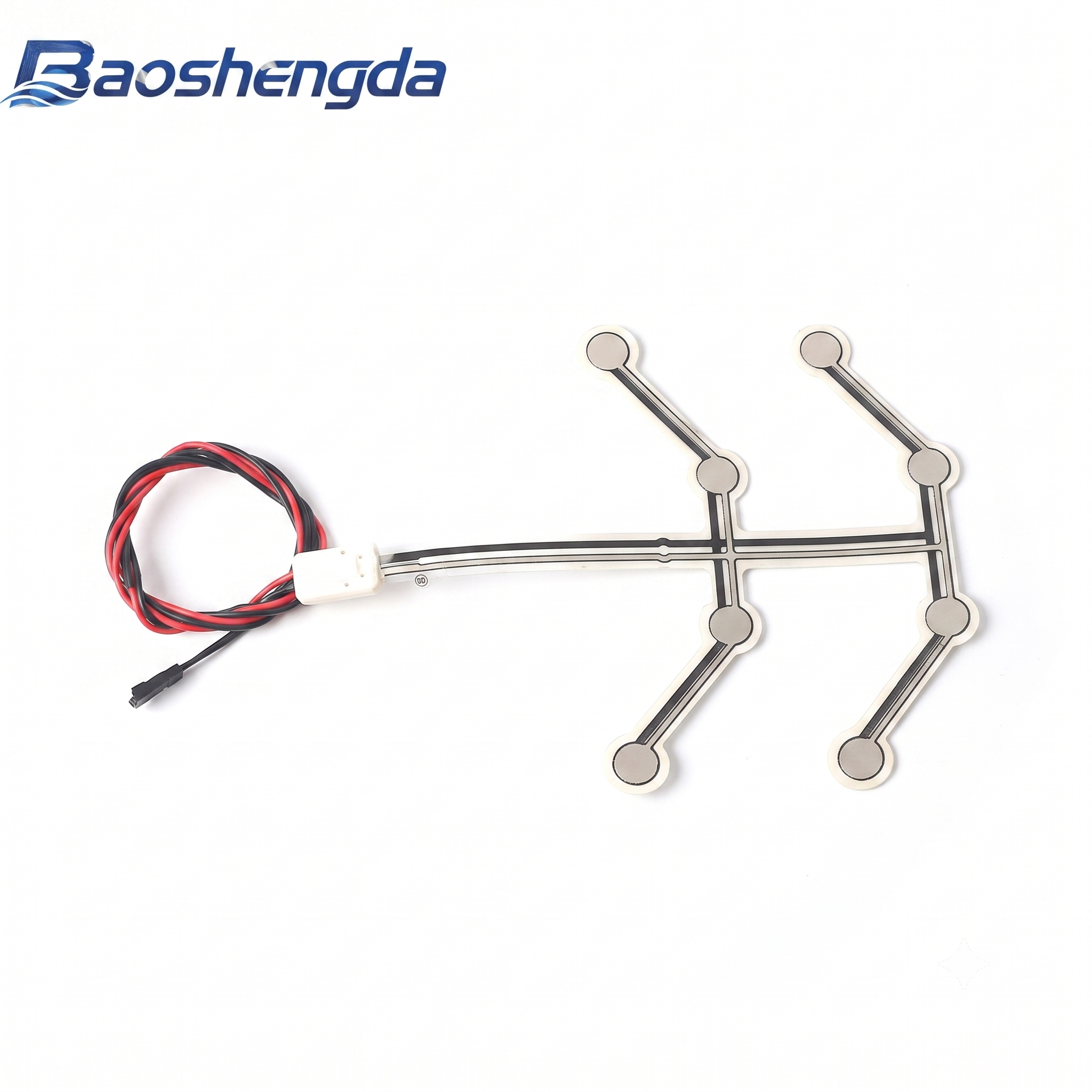
A robot pressure-film drawing with six sensing pads does not, by itself, specify six independently readable channels. The electrical connections and readout method decide whether those pads produce separate readings, share a return, or contribute to one combined signal. Before requesting a firm FSR quotation, label the physical zones and map each one to the intended circuit and connector terminals. An initial enquiry can start with a sketch and the required output. The supplier can then identify missing inputs. Do not order an array from its outline alone if the controller must distinguish where contact occurred.
The cover is a real Baoshengda sample photograph. It shows six circular regions, branching printed paths, a common tail area, lead wires and a connector. It does not establish six independent electrical channels or show a sensor installed on a robot.
What the new robotic-skin architecture establishes
Published on September 23, 2026, the SkinAxis robotic-skin study describes a soft patch coupled to a compact three-dimensional force sensor. The researchers combine elastomer properties, a load-transmission plate and a sensor support sleeve, and evaluate touch localization as well as impact behavior. The reported system uses a Hall-effect sensing architecture. It is not a printed FSR array.
A robot developer can misread this result when the developer sends a supplier a multi-pad film drawing while expecting localized contact information. The study's localization result belongs to its complete sensing and mechanical architecture, including its models. It cannot be transferred to another component simply because both designs have contact regions. Nor does it establish a safety function for a custom film.
For an FSR component enquiry, the practical takeaway is narrower: define how physical contact becomes an identifiable electrical reading. A zone layout, circuit drawing and readout description should agree before the component scope is quoted.
Put physical zones and electrical nodes on different drawing layers
Give every intended contact region a stable zone ID, such as Z-A or Z-B. Use separate labels for electrical nodes. A circle on the mechanical drawing identifies a location. It does not say which conductor the controller measures.
The following table is a design-review aid, not a description of the photographed sample's hidden circuit.
| Proposed arrangement | What the buyer needs to resolve | Evidence to send |
|---|---|---|
| Individually wired sensing elements | Which terminal pair belongs to each zone, and where the measurement circuit sits | Zone-to-terminal schedule and circuit schematic |
| Separate zone lines with a shared return | How each zone is measured, and whether the shared path affects the intended reading | Named common node, individual zone nodes and readout circuit |
| Row-and-column addressing | How the controller selects intersections and handles simultaneous contacts | Row/column map, scan method and multi-contact requirement |
| Zones connected into one passive measurement path | Whether a combined response is sufficient, rather than independent location information | Connection diagram and a written combined-output requirement |
A shared conductor is not automatically a design error. It may be part of an appropriate readout. The error is treating different architectures as interchangeable when purchasing the film. A buyer expecting separate zone readings can approve the correct outline and still receive a component that cannot supply the required information through the specified interface.
Start with one contact scenario. Must the controller distinguish Z-A from Z-B, or does it only need to know that either region was pressed? Then state what happens when both are loaded. That answer determines which circuit questions must be resolved before quoting.
Make the terminal map readable from the assembly side
A useful connection schedule ties together zone ID, node name, terminal ID and controller input. Specify the connector viewing direction, mating face and terminal numbering convention. If the film is turned over during assembly, a left-to-right illustration can become a mirrored pin assignment unless the drawing fixes the orientation.
Mark the trace route, tail exit and lead-wire transition on the mechanical drawing. Include the connector housing and mating component reference when known. Wire colors may help assembly, but they are not a substitute for a controlled terminal map. A replacement cable can preserve colors while changing its pin order.
Do not infer terminal count or circuit topology from a cover photograph. On the sample shown here, the regions and routing are visible. Contact assignments and internal connections are not documented by the image. The supplier needs the electrical drawing to confirm the requested interface.
Baoshengda's custom FSR pressure-sensor options include point-array layout, tail and connector review. Those options support a component discussion. They do not mean every outline can deliver any requested channel architecture. Routing space, isolation and the customer's readout concept need project-specific confirmation.
Approve the channel map before interpreting a sample curve
For sample review, agree on a test that identifies a zone as well as detecting a response. Apply the defined contact to one named region at a time and record the expected controller input. Repeat for every region, then apply the simultaneous-contact combinations relevant to the application. Specify the load method and readout conditions so a wiring check is not confused with a force-calibration test.
Check the connection schedule against the sample's actual mating orientation. Compare unloaded and loaded readings using the agreed circuit. An ordinary continuity check can confirm conductor connections, but it does not prove force sensitivity, channel separation or the ability to distinguish two simultaneous contacts.
Keep firmware thresholds and robot behavior outside the film-only approval. The equipment developer owns signal processing, diagnostic coverage and the decision to slow, stop or continue motion. A prototype response or a correct terminal map is not evidence of a safety-rated robot function.
Move from an enquiry sketch to a released circuit drawing
For an initial enquiry, send the rough outline, intended contact locations, required output and likely quantity. If the circuit is undecided, say so. Ask for a feasibility review rather than presenting the zone count as a finished channel specification.
For an indicative quotation, identify assumptions still open: independent or combined readings, readout ownership, connector type, tail direction and available routing space. Keep those assumptions on the quotation so changing the architecture does not become an unexplained sample revision.
For sample approval, provide the proposed circuit, zone-to-terminal schedule and the agreed single-zone and simultaneous-contact checks. For production release, freeze the approved mechanical and electrical revisions, mating orientation, inspection method and permitted substitutions.
A compact enquiry package can include:
- An outline sketch with zone IDs and active-region dimensions.
- The required result: contact present, zone identity or relative response by zone.
- A circuit concept, or an explicit request to review an undecided concept.
- A connector view with terminal IDs and the intended controller inputs.
- The contact surface, support and sample test conditions.
- Expected sample and production quantities, with open assumptions listed.
Use Request Quote for an FSR layout and connection review to send that package. The first question to resolve is whether the controller needs one contact signal or separately identifiable zones. The zone-to-channel map should make that answer visible before the film drawing is released.
Need help reviewing a structure?
Send your drawing, photos, application, and quantity. Baoshengda can help check the structure before sampling.
Send Drawing for Quote