
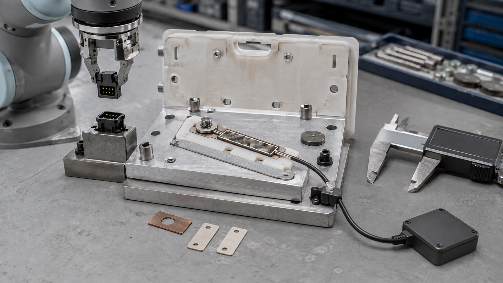
A custom FSR for robotic connector assembly should not be quoted from a target insertion-force value alone. The supplier also needs the real contact footprint, rigid backing, preload, allowable travel, hard stop, working force range, detection objective, electronics, tail and connector. These inputs determine how load reaches the sensing area and what a repeatable output means. Freeze them as one fixture stack, then approve three sample stages: bare sensor, assembled contact fixture and robot-cell cycle. Use the FSR for defined threshold or comparative evidence only. Do not treat it as the robot's force-control sensor, safety function or proof of connector quality by itself.
Why connector assembly makes fixture details commercially important
A September 3 FANUC America IMTS 2026 announcement describes a dual-arm robotic connector-assembly demonstration that uses vision and force data for connector insertion and assembly tasks. The announcement does not say that the application uses an FSR, does not specify a Baoshengda component and does not establish a supplier relationship.
The useful buyer signal is narrower. Connector insertion is a load-path problem as well as a motion problem. If a sourcing team wants a thin force-sensitive resistor under a contact puck, nest or support surface, the mechanical stack becomes part of the sensing specification. Two fixtures can apply the same nominal force and produce different output because the footprint, backing stiffness, local bending, preload and stop position are different.
That is why a request such as "quote an FSR for a 30 N insertion" is incomplete. The force value may describe the robot, the connector, a fixture limit or a desired threshold. It does not yet describe what reaches the sensing area.
A force target is not a quote-ready sensor input
Before discussing film outline or price, identify the event that the FSR is meant to observe. Is it confirming that a connector is present in the nest, detecting first contact, comparing one insertion cycle with a qualified reference, or warning that a fixture pad has not returned? Each role creates a different working range, threshold method and sample plan.
Then describe the contact geometry. A narrow metal edge, a rounded polymer puck and a broad elastomer pad distribute load differently. If the actuator touches only part of the sensing zone, output can shift with small placement changes. If the backing plate flexes, the fixture can absorb travel that the buyer intended to measure. If preload already compresses the stack, the released value is no longer a true zero reference.
Use the following decision table before requesting comparable quotations:
| Decision to freeze | Evidence to send | Why it changes the quotation |
|---|---|---|
| Detection role | Part-present, first-contact, comparative cycle or threshold objective | Defines whether repeatability, threshold separation or working-range mapping matters most |
| Contact footprint | Actuator drawing, material, edge radius and allowed position tolerance | Controls local pressure and how much of the sensing zone is loaded |
| Backing and support | Fixture section, plate material, flatness and supported area | Changes bending, local strain and output stability |
| Preload and travel | Assembly stack, released gap, preload range and mechanical stop | Establishes the starting condition and prevents overload assumptions |
| Electrical readout | Supply or divider circuit, sampling method and decision threshold | Makes sample data comparable across the buyer and supplier fixtures |
| Tail and connector | Tail datum, bend keepout, contact side, mating connector and strain relief | Prevents a good sensing element from failing through the integration path |
A supplier can quote conditionally when some inputs are unknown, but the quotation should list those assumptions. Hidden assumptions are more expensive than visible options because they reappear during sample approval.
Freeze the contact fixture as one controlled stack
Treat the actuator, contact puck, sensor, adhesive, backing plate, preload feature and hard stop as one controlled stack. Give every part a revision. A photograph can show where the pieces sit, but the drawing should show the load direction, supported area, contact footprint, nominal stack height and allowable movement.
Keep the mechanical stop physically separate from the sensing function. The stop protects the fixture from excess travel; the FSR provides an electrical response within a defined range. If the stop position changes, the peak load reaching the sensor can change. If the stop bottoms before the target event, the sensor may report a stable value while the connector is not fully seated. If the stop never engages, the sensor may be exposed to uncontrolled compression.
Preload needs its own tolerance and measurement method. State whether preload comes from a shim, spring, elastomer, fastener torque or closed fixture gap. Record the released output after the final assembly has settled. Do not subtract an arbitrary baseline in software and then call the mechanical stack controlled.
For supplier comparison, send one section view with named datums rather than separate sensor and fixture sketches that cannot be overlaid. The same datum should control the sensing-zone position, contact puck and tail exit.
Separate useful FSR evidence from robot force control
An FSR can be useful when the buyer wants a defined threshold, a comparative signature against an approved fixture or a part-present indication. These are component-level decisions that can be tested with a controlled contact stack and readout circuit.
The FSR should not be presented as the robot's closed-loop force or torque sensor unless the complete system owner has designed and validated that architecture. It is also not a safety-rated protective device, not a substitute for connector-maker insertion-force limits and not proof that electrical contacts are fully engaged. A connector can reach a force threshold because of misalignment, contamination or fixture interference. The force evidence must be combined with the buyer's position, vision, continuity or functional checks as applicable.
Define which system owns the final accept or reject decision. The FSR supplier can provide the sensor sample, agreed electrical characterization and dimensional evidence. The robot integrator owns motion, tool alignment, control logic and cycle acceptance. The connector owner defines mating geometry and functional acceptance. Safety decisions remain with the qualified system team.
Approve three sample stages instead of one golden number
Start with a bare-sensor fixture that applies the intended contact footprint to the intended sensing zone. Map released and loaded readings across the proposed working range. Record the actuator, backing, dwell time, loading rate, measurement circuit and environmental condition. This stage checks whether the construction and readout direction are suitable before the full robot fixture adds more variables.
Next test the assembled contact fixture. Include the actual adhesive, backing, preload, shims, hard stop, tail route and connector. Repeat measurements after assembly and after the fixture has been opened and reassembled. The goal is not to make every sample produce one identical raw value. It is to determine whether the agreed decision bands remain separated under realistic assembly variation.
Finally run a controlled robot-cell study using the released fixture revision. Compare known accepted cycles with deliberately bounded non-accepted conditions chosen by the system owner. Possible cases include missing part, offset contact, incomplete seating or a fixture pad that does not return. Retain robot program, tool, fixture, connector lot, sensor, readout and software revisions. Do not generalize one laboratory trace into an unlimited production guarantee.
A sample report should state what was measured and what remains outside scope. A pass at the bare-sensor stage does not approve the assembled fixture. A fixture pass does not validate the full robot process.
Keep the tail and connector inside the measurement path
A sensing pad can perform correctly while the installed signal becomes intermittent. Control the full flexible tail, first-bend keepout, stiffener, contact side, conductor pitch, connector orientation, latch access and strain relief. Show where robot motion, fixture opening or service handling could pull or rub the route.
Measure continuity and output at the same electrical point the buyer will use. If the supplier measures at exposed tail contacts but the buyer reads through a cable and connector, preserve both results during approval. This separates a sensing-zone problem from an interconnect problem.
For compact tooling, a custom FSR pressure sensor with a controlled sensing zone, tail and connector can be reviewed against the buyer's contact fixture. Feasibility still depends on the actual outline, load path, electrical circuit, mounting method and expected variation. A webpage or catalog image cannot settle those items.
Define the component-supplier boundary in the quotation
The FSR supplier can review the sensing outline, electrode or printed-circuit geometry, tail construction, contact termination, connector option, adhesive outline and agreed sample-level electrical response. It can build samples to controlled inputs and report results from an agreed fixture and circuit.
The supplier cannot validate robot motion, connector mating quality, finished-cell safety, machine guarding, functional safety, production capability or regulatory compliance without the complete system requirements and responsible owners. It also cannot guarantee a universal force value when the buyer changes contact footprint, backing, preload, stop, temperature, readout circuit or decision algorithm.
Put these exclusions beside the assumptions, not in a generic footer. A quotation should identify buyer-supplied fixtures and samples, supplier-built coupons, test ownership, acceptance records and the change events that require reapproval.
Send one drawing, sample and RFQ evidence package
Include these items to turn the request into an engineering review rather than a force-number guess:
- Intended event: part present, first contact, comparative cycle or threshold decision.
- Connector and robot-cell context, while keeping proprietary geometry limited to the controlled review package.
- Sensor outline, active sensing zone, mounting datum and allowed position tolerance.
- Contact puck or actuator drawing with material, edge radius, footprint and alignment tolerance.
- Fixture section showing rigid backing, adhesive, preload feature, shims, available travel and independent hard stop.
- Expected working range, overload boundary, dwell, loading rate and cycle profile when known.
- Electrical circuit, supply context, sampling rate, filtering and decision threshold ownership.
- Complete tail route, bend keepout, contact side, pitch, stiffener, connector and mating-part definition.
- Bare-sensor, assembled-fixture and robot-cell sample stages with separate acceptance criteria.
- Required records, sample quantity, production quantity range, change control and return or failure-analysis plan.
Send this controlled package through the Request Quote page. The first response can then identify what is quote-ready, what needs a fixture sample and which assumptions must remain conditional before tooling or production approval.
Need help reviewing a structure?
Send your drawing, photos, application, and quantity. Baoshengda can help check the structure before sampling.
Send Drawing for Quote