
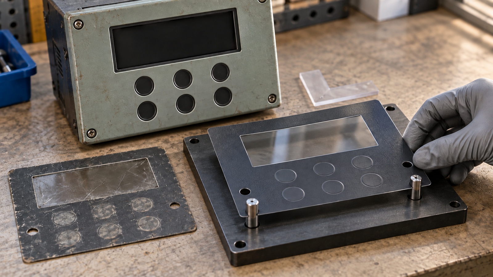
For a refurbished industrial HMI, a faceplate photo or scan is not enough to release a replacement graphic overlay. Use it to recover visible layout, wear history and missing artwork clues, then rebuild a controlled master around the enclosure cut line, display opening, key centers, indicator windows, adhesive land and agreed datums. Approval should include a mounted first article, not only a loose printed film. This protects service teams from shifted windows, off-center legends, blocked keys, exposed adhesive and revision drift. Buyers should send the most representative physical sample, front and rear images, a scaled scan, enclosure data and acceptance ownership in the RFQ.
Why refurbishment creates two different records
A September 9 Siemens announcement about manufacturer-refurbished automation products names drives, controllers and HMI panels and says its standardized process can include visual restoration where necessary. That is useful current context for a long-life equipment problem: a working operator panel may need its exterior face restored even when its original artwork file, supplier drawing or approved color record is no longer available.
The announcement does not disclose any faceplate construction, graphic-overlay process or Baoshengda relationship. It also does not make an aftermarket film supplier responsible for the original manufacturer's electrical, software, cybersecurity, conformity or functional tests. The component decision is narrower. If an OEM, refurbisher or service organization needs a replacement face surface, which evidence is strong enough to reproduce the overlay without turning wear, camera distortion or an old field modification into the new production master?
The answer starts by separating two records:
- The installed faceplate is condition evidence. It shows what operators touched, where abrasion occurred, which openings exist and which visible functions may still matter.
- The released overlay master is production authority. It defines geometry, artwork, finish, color, adhesive and revision in a form that can be inspected and repeated.
Confusing those records is the main transfer risk.
Treat the scan as recovery evidence, not release authority
A square, high-resolution flatbed scan is usually more useful than a handheld photograph for recovering two-dimensional artwork. It can help trace a perimeter, estimate a window outline, identify missing legends and compare zones. A photograph is still useful for surface finish, installation order, wear, enclosure relationship and evidence that may disappear when the overlay is removed.
Neither source is automatically dimensionally authoritative. A photograph can contain perspective error, lens distortion and unknown camera distance. A scan can still capture a part that has stretched, curled, shrunk, crept under heat or been trimmed during an earlier repair. A worn edge may no longer represent the original cut line. Adhesive residue can enlarge an apparent perimeter. A darkened display border can hide the true visible window. A field technician may also have fitted a non-original revision years earlier.
Use the image set to ask better questions. Do not use pixels alone to answer them. At minimum, confirm one known scale reference, the condition of the physical sample and the relationship between the film and the current housing.
Rebuild the master around physical datums
A controllable replacement begins with a datum scheme, not with a prettier trace of the old face. The datum scheme should connect the overlay to features that the assembly team can find again on the enclosure or fixture.
A practical scheme may use:
- one primary origin tied to a stable enclosure edge, locating hole or fixture feature;
- a second direction control that prevents rotation;
- the display opening and active viewing area as separate dimensions;
- key, indicator and cutout centers dimensioned from the same origin;
- corner radii, outside cut line and minimum adhesive land;
- any emboss centers and height limits that affect the switch or key below;
- a controlled print file with revision, color references and finish zones.
Do not silently average misaligned evidence. If the scan, housing measurement and old supplier drawing disagree, record the disagreement and decide which physical interface governs. For example, the display window may need to follow the active display and bezel, while a legend group follows the approved artwork. The outside film edge may follow an adhesive recess rather than the worn sample edge.
This is where a specialist in custom graphic overlay film panels can help review the component drawing, print zones, windows, embossing, finish and adhesive boundary. The buyer still owns the mating enclosure, display and functional definition.
Decide what each evidence source can release
| Evidence available | Useful decision | Do not release from it alone | Next control |
|---|---|---|---|
| Angled front photograph | Installed appearance, wear zones and relative feature location | Cut line, window dimensions or key-center coordinates | Add a square photo and known scale reference |
| High-resolution flatbed scan | Artwork recovery and approximate two-dimensional tracing | Final size when the old film may be distorted or trimmed | Compare with housing datums and physical measurements |
| Worn physical overlay | Material feel, finish, layer order and actual opening relationships | Original color, unworn texture or unmodified revision | Record condition and retain it as a reference sample |
| Enclosure or bezel drawing | Mounting recess, cutouts, edges and stable datums | Artwork meaning, color or operator labeling | Overlay the reconstructed print file on the mechanical datum drawing |
| Original artwork without dimensions | Legend content, symbol shape and print grouping | Perimeter, window, emboss or adhesive geometry | Link artwork to a dimensioned overlay master |
| Mounted first article | Real fit, window alignment, edge clearance and operator-zone registration | Long-term system reliability or electronics performance | Approve the component evidence and keep system validation separate |
This table is also a useful quotation filter. If a buyer has only an angled photograph, the supplier can quote an evidence-recovery stage, but a production price based on assumed final geometry may hide later redesign and sample costs. A better quotation separates data reconstruction, prototype tooling when needed, mounted sample approval and production volume.
Approve a mounted first article, not loose film alone
A loose overlay can look correct on a light table and still fail after installation. The mounted first article checks whether the reconstructed master actually belongs to the current enclosure revision.
Review the installed sample in a repeatable order:
1. Align the outside cut line and datum features to the housing. Record any fixture or assembly method used.
2. Check the visible display area from normal viewing positions. Separate the transparent window size from the printed border and the display's active area.
3. Confirm key and indicator centers against the hardware below. If embossing is used, check that each dome or rim supports rather than interferes with the intended action.
4. Inspect edge clearance and adhesive land. A film that reaches a housing radius, screw boss or contamination path may lift even when its flat dimensions appear correct.
5. Compare color, gloss, texture and window clarity under agreed lighting. Do not treat a phone photograph as the only color approval record.
6. Exercise the relevant keys or controls through the installed overlay. This checks physical alignment, not controller logic or safety performance.
7. Record the sample revision and any approved deviation before production artwork is frozen.
If several refurbishable HMI models share a similar face, do not assume one overlay fits all of them. A common visual family can still have different display apertures, key spacing, housing radii or adhesive recesses. Maintain a variant matrix linked to actual mechanical evidence.
Make supplier replacement a revision-control project
Supplier replacement often begins because an old source is unavailable, the artwork file cannot be found or field spares are inconsistent. The quickest-looking path is to copy the most representative surviving part. The safer path is to create a controlled bridge from surviving evidence to a new released record.
That bridge should identify:
- which old sources were received and their condition;
- which dimensions came from the enclosure rather than the scan;
- which artwork was reconstructed or redrawn;
- which colors and finishes were matched to a retained reference;
- which assumptions remain open;
- which mounted sample closed each open item;
- which revision becomes the new purchasing reference.
Keep the old faceplate, reconstructed master, redline and approved sample linked. Future buyers then compare a replacement batch with a known release package instead of repeating forensic recovery from another worn field unit. That is the durable value of the project. The new overlay is not just a cosmetic copy. It is a controlled service part with traceable evidence.
Supplier boundary: the overlay is not the whole HMI
Baoshengda can review and manufacture the graphic-overlay component to a released drawing, including the outside profile, display and indicator windows, printed graphics, selected surface finish, emboss features and adhesive pattern when those inputs are defined. Sample work can support comparison of loose and mounted component geometry.
The boundary is equally important. A graphic-overlay supplier does not refurbish or certify the original HMI electronics, firmware, display, controller, cybersecurity, machine-safety circuit, ingress rating or regulatory conformity unless those services are separately and explicitly in scope with suitable evidence. A generated cover image is an engineering illustration, not a customer case or proof that a particular OEM panel was restored.
If a key does not respond after the new overlay is fitted, the cause may sit below the overlay in a membrane switch, elastomer, discrete switch, PCB, connector, controller input or software state. Define the fault-isolation and acceptance owner before blaming the face film.
Drawing, sample and RFQ checklist
Send the most complete available package, even when some original files are missing:
- front and rear photographs taken square to the panel, plus installed-context images;
- a high-resolution flatbed scan with a verified scale reference;
- the most representative physical overlay sample, with its condition and suspected revision identified;
- enclosure, bezel, display and key-location drawings or measured datum records;
- outside cut line, display window, indicator windows, holes, key centers and corner radii;
- artwork in editable vector form when available, plus language and symbol ownership;
- color reference method, gloss or texture zones, window clarity and any print-opacity requirements;
- emboss type, location and height limits where applicable;
- adhesive pattern, excluded zones, bonding surface and installation method;
- cleaning agents, temperature, UV, abrasion or chemical exposure relevant to the component;
- prototype quantity, production quantity, model variants and revision history;
- the mounted first-article checks, acceptance bands and person authorized to approve deviations.
When these items are ready, use the Request Quote page to send the non-confidential scope. Keep customer-specific artwork, serial data and sensitive equipment drawings in the agreed controlled exchange rather than a public article or casual email thread.
Need help reviewing a structure?
Send your drawing, photos, application, and quantity. Baoshengda can help check the structure before sampling.
Send Drawing for Quote