
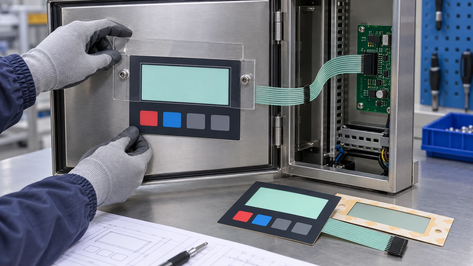
For a refrigeration control-panel retrofit, freeze the display aperture and installed service interface before asking a supplier to redraw the front panel. Confirm the new display's active area and outer envelope, the legacy enclosure datums, the bezel or adhesive land, any local physical keys, and the route to the mating connector. A first enquiry can begin with old and new display information plus enclosure photographs. Keep unresolved dimensions as quotation assumptions. Approve a loose component sample first, then repeat the review in a representative enclosure before releasing matched mechanical, artwork, circuit and inspection revisions for production.
A split display and controller changes the retrofit question
GEA's September 21 announcement of the Omni NG control panel describes a heating and refrigeration control platform that replaces the earlier integrated industrial PC arrangement with a separate touchscreen monitor and processing module. GEA also describes backward compatibility with the preceding platform. That is current evidence that controller generations can change their physical architecture even when an upgrade path is intended.
The announcement does not identify Baoshengda, specify a custom membrane panel or disclose the enclosure details needed for another manufacturer's retrofit. The useful buyer lesson is narrower: “backward compatible” at the control-platform level does not automatically freeze the front-panel aperture, bezel, cable route or service access. Those component interfaces still need controlled evidence.
Baoshengda's first-party references visibly show complete membrane-panel faces with large display windows, multiple key zones, flexible tails and connectors. A rear reference also shows the relationship between the window opening, adhesive construction and tail. A separate factory photograph shows hands handling layered membrane circuits during assembly. This evidence supports a component-level review method. It does not prove compatibility with a refrigeration controller, display optics, enclosure sealing, software, cybersecurity, dimensions, tolerances or equipment release.
Freeze the aperture from the active image outward
Start with three rectangles that are often confused. The active display area is where information actually appears. The display module outline is the physical glass, frame or housing that must fit behind the front. The panel aperture is the visible opening through the overlay or bezel. They are related, but they are not interchangeable.
Ask for the new display's active-area drawing and complete mechanical envelope. Overlay it on the controlled legacy enclosure drawing. Check whether the existing opening hides useful pixels, exposes an inactive border, conflicts with a touch zone or leaves insufficient support around the window. Record the viewing direction and intended operator position if parallax or edge masking matters to the equipment owner.
Do not select a larger clear window merely because it appears safer. A larger aperture can reduce the printed border and adhesive land, reveal module edges or move a narrow bridge closer to a key zone. A smaller aperture can mask information or interfere with a touch surface. The useful decision is the controlled relationship among the active image, module envelope, aperture and mounting surface.
| Retrofit decision | Evidence for the first enquiry | Quotation assumption if missing | Mounted-sample check |
|---|---|---|---|
| Display aperture | New active-area and module-outline drawings, legacy front photo | Provisional visible opening and border width | No active information is masked and no inactive edge is unintentionally exposed |
| Mounting datum | Enclosure drawing, cutout, studs, recess and flat support land | One named datum origin and provisional tolerance stack | Panel seats without forced alignment, edge interference or distortion |
| Local physical inputs | Existing key map and functions that remain local | Only listed non-safety inputs are inside the component scope | Key location, support and actuation are checked in the installed condition |
| Tail or cable route | Exit side, mating-header position, door motion and service cover | Provisional length, bend direction and connector orientation | Full service movement occurs without pinch, sharp fold or connector load |
| Window and front finish | Lighting, viewing, cleaning and artwork requirements supplied by the buyer | Proposed clear or filtered window and surface finish | Appearance and readability are reviewed under the buyer's representative condition |
Use stable enclosure datums, not a photograph alone
A front photograph can start the discussion, but it cannot define the retrofit. Identify one stable horizontal datum and one stable vertical datum on the enclosure or mounting plate. Dimension the aperture, panel outline, holes, studs, recess and tail exit from those datums. Include corner radii and the actual flat land available for adhesive, gasket or a rigid backer.
If the legacy part is the only available reference, label measured values separately from released dimensions. Photographs can document the sample condition, while a dimensional report or authorized scan can identify what was measured. Do not silently convert one worn service part into the production master. Paint build-up, bent metal, field drilling and compressed gasket material can all change what a loose sample appears to require.
For the first quotation, unresolved tolerances may remain assumptions. State which dimensions are measured, which are copied from an old drawing and which will be confirmed on the equipment owner's enclosure. This lets a supplier price tooling and sample work without pretending that a preliminary fit is already approved.
Keep local panel functions separate from controller features
A refrigeration control platform can include software screens, remote access, historical data and network functions. A passive front-panel supplier should not quote those functions as if they belong to a graphic overlay or membrane circuit. Define only the local component features that remain in scope, such as a window, printed legends, non-safety tactile keys, LEDs when the electronics interface is supplied, adhesive, backer, flexible tail and connector.
The equipment maker or control-system owner remains responsible for the display module, processing hardware, wiring, software behavior, refrigeration logic, alarm priorities, machine safety, cybersecurity, network access, final enclosure performance and equipment validation. If an emergency or safety-related function exists, its architecture and approval stay outside a decorative or passive panel decision unless separately designed and controlled by the responsible system team.
The supplier can still help expose interface gaps. Baoshengda can compare window geometry with the supplied display envelope, review panel-stack and mounting inputs, identify missing tail or connector information, manufacture a controlled component sample and document component-level inspection criteria. That support is useful because it makes assumptions visible before tooling and installed validation.
Approve the loose sample and mounted interface for different reasons
The loose sample should confirm the panel outline, window position, visible artwork registration, layer stack, key zones, tail construction, connector identity and basic circuit mapping when a membrane switch is included. It is also the right stage to compare the sample with the released drawing and approved visual reference.
The mounted check answers different questions. Fit the sample to the representative enclosure using the intended support, fasteners, adhesive or gasket condition. Confirm that the stable datums locate the component without forcing it into place. Review the complete window from the intended viewing direction. Move the door or service cover through its full path while watching the tail, cable, connector and nearby hardware. Record any temporary spacers, prototype cables or substitute materials so they cannot become an accidental production standard.
A clean bench fit is not equipment release. The equipment owner should perform the necessary optical, electrical, environmental, cleaning, software and system checks under its controlled method. The supplier's mounted-interface record should state what was observed and avoid turning one sample into an unsupported performance claim.
Start the enquiry before every production file is complete
Send the information already available:
- straight-on and rear photographs of the legacy panel and enclosure;
- controlled legacy drawing or clearly labelled measured dimensions;
- new display active-area and full mechanical-envelope drawings;
- aperture, enclosure datums, mounting land, holes, studs and recesses;
- local key, window, artwork and finish requirements that remain in component scope;
- tail exit, connector target, service-door motion and internal clearance;
- sample quantity, expected production quantity and reason for the retrofit.
Ask the quotation to list its assumptions for aperture, material, finish, adhesive or backer, key construction, circuit, tail, connector, tooling and inspection. After the loose and mounted samples are approved, release one matched package: mechanical drawing, artwork, layer stack, circuit and pinout when applicable, connector specification, inspection plan, approved sample identity and change-control rule.
Review integrated HMI panel component options and supplier scope before freezing the retrofit package. Then send the legacy enclosure and proposed display evidence for a component-level quotation review. The useful next step is not a complete refrigeration-system specification. It is a controlled comparison that shows which physical interfaces are stable and which remain assumptions.
Need help reviewing a structure?
Send your drawing, photos, application, and quantity. Baoshengda can help check the structure before sampling.
Send Drawing for Quote