
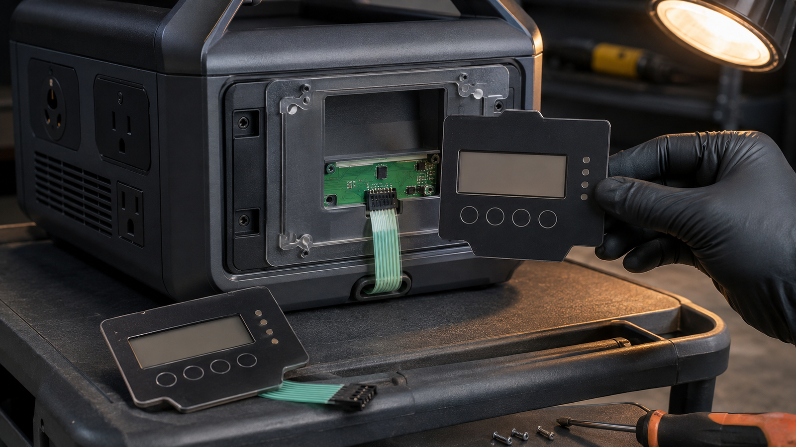
For a portable or home backup power station keypad replacement, approve the spare only after the old and new interfaces pass the same offline-action, status-light, tail-routing and connector checks. A copied faceplate is not enough. Freeze which local key works during startup, app loss, display loss, alarm acknowledgement and controlled shutdown. Map every indicator window to a named device state. Then confirm overlay datums, adhesive support, tail contact side, connector orientation and mounted service access. Release the replacement only after scripted outage and wake tests show that the complete device responds as intended.
Start the replacement from offline actions, not appearance
A field spare can look identical to the original and still change the way the equipment behaves. Artwork may place a power symbol, mode key or status window in the expected location while the circuit beneath it reaches a different controller input. A replacement tail can have the same conductor count but reverse the contact side. A connector can mate mechanically while the pin assignment is wrong. An indicator can light during a test yet represent a different device state because polarity, current limit or software ownership changed.
Begin with a list of actions that must remain available without the phone app or network connection. Typical candidates include wake, local power control, output enable, display toggle, alarm acknowledgement and controlled shutdown. Do not assume every product needs all of them, and do not treat a physical key as an automatic safety control. The system owner must state which actions exist, who may use them, the required power domain and the visible response.
For each action, record the original revision, proposed replacement revision and acceptance method. This delta sheet becomes the commercial boundary for the replacement quotation. It prevents a visually convincing sample from being approved before its electrical and state behavior are understood.
Use the current backup-power launch as limited market context
A September 4 Jackery announcement about its portable, whole-home and emergency backup energy portfolio shows current market attention around connected power products and backup use. The announcement does not disclose the internal keypad construction, does not say that a membrane switch is used and does not identify Baoshengda as a supplier. It also provides no evidence for the replacement design discussed here.
The useful sourcing signal is broader. When a product family spans portable and home backup use, buyers may need service spares that preserve local operation across different installation, storage and outage conditions. App connectivity and advanced energy functions do not remove the need to define what the front interface does when the app, display or network is unavailable. That turns a market launch into a durable component question: can a replacement front interface reproduce the intended local action and status evidence without creating an undocumented revision?
This article addresses that component decision. It does not evaluate the announced products or their energy, safety or runtime performance.
Freeze one replacement delta sheet before pricing
The quotation package should make differences visible instead of asking the supplier to infer equivalence. A useful delta sheet separates appearance, mechanical fit, circuit definition, optical behavior and system response.
| Replacement item | Evidence to freeze | Sample decision | Failure hidden by appearance |
|---|---|---|---|
| Offline key ownership | Action name, enabled states, power domain and controller input | Exercise every local action during startup, normal use, app loss and recovery | Key closes correctly but the controller ignores it in a required state |
| Indicator windows | Window position, color or optical requirement, polarity, drive limit and named state | Compare off, active, fault and transition states in the mounted unit | Light is visible but communicates the wrong state |
| Overlay and adhesive | Perimeter datum, window and key positions, adhesive land, gaps and surface preparation | Inspect registration and support after mounting and environmental conditioning | Loose panel passes, but unsupported areas lift or change key feel |
| Flexible tail | Exit datum, length, bend keepout, contact side, pitch, stiffener and trace-to-pin map | Route through the production-intent opening with the cover open and closed | Tail mates only when twisted or rubs during service |
| Connector interface | Mating part, insertion direction, latch access, orientation and retention | Seat, inspect and rework the connector using the intended service access | Connector fits but is reversed, partly seated or inaccessible |
| Complete device response | Released controller and software revision, expected state before and after each action | Run recorded outage, wake and shutdown scripts | Component works electrically while the assembled product responds incorrectly |
The table should name evidence owners. The interface supplier can confirm the component drawing and agreed sample tests. The product owner must approve action meanings, controller behavior and system-level acceptance.
Separate app, display, key and indicator ownership
Connected equipment often has several ways to present or request the same function. The app may show a control that also appears on the local display. A physical key may issue a request that software accepts only in selected states. An indicator window may be driven by the interface circuit, the main controller or a separate light board. Replacement work fails when these owners are treated as interchangeable.
Create an ownership matrix with four columns: app action, display action, physical key and indicator response. Add rows for powered off, starting, ready, output active, warning, fault, app disconnected, display blank, controlled shutdown and service mode. In each cell, mark available, unavailable or conditional. Name the controller input or software event that receives a key action, and the electrical output that drives each indicator.
If a function exists in both the app and a key, state which one has priority and what happens when requests arrive together. If the display is blank, identify whether the physical key still has power and whether feedback comes from an indicator, sound or restored screen. If an indicator flashes, specify the state and cadence owner rather than asking the membrane-switch supplier to guess a firmware pattern.
This matrix does not need to expose confidential firmware. It needs enough controlled information to prevent the replacement circuit and optical windows from being approved against the wrong assumptions.
Prove housing, adhesive, tail and PCB fit as one route
A membrane keypad replacement is a routed assembly, not a flat graphic. Start at the visible overlay perimeter and follow the physical path to the controller. The drawing should include the housing datum, bezel step, support under each key, display-window registration, adhesive landing, tail exit, first bend, strain-relief feature, stiffener, connector orientation and PCB location.
Test the production-intent housing rather than pressing a loose sample on a bench. Rigid support and local gaps can change tactile response. A bezel edge can load the overlay. A narrow adhesive land can lift after temperature cycling or service opening. A tail that looks acceptable with the bezel open can pull against the connector when the cover closes.
Record photos of the route before and after closing the service panel, but remove customer marks and confidential geometry from the RFQ copy. Measure only the datums needed for feasibility and acceptance. If the old part has been discontinued, identify which dimensions come from a controlled drawing and which were measured from a field sample. Mixing those sources without labels can preserve wear or deformation as if it were the design intent.
For a replacement requiring fixed local keys and visible state windows, a backlit membrane switch with a defined overlay, optical zones, flexible tail and connector can be reviewed as one option. Final feasibility depends on the actual circuit, lighting method, stack, enclosure, environment and acceptance plan.
Run mounted outage and wake scripts before spare approval
The component sample needs electrical checks, but the service spare is approved only when the mounted device completes the intended scripts. Use the released product revision and record the initial condition, operator action, controller input, visible response, final state and recovery route.
At minimum, consider these scripts where they apply:
1. Wake the unit from its defined low-power state using the local interface.
2. Disconnect or disable the app path, then exercise each required local action.
3. Blank or restart the display while checking whether the approved physical action and indicator response remain available.
4. Start the unit with the service battery state and loads defined by the system owner.
5. Acknowledge a warning without clearing the underlying condition.
6. Hold a key through a software restart and verify debounce and recovery behavior.
7. Open and close the service bezel, then repeat the key and indicator checks without moving the tail.
8. Perform the controlled shutdown and confirm the specified final indication.
Do not turn these scripts into an unsupported claim that the keypad provides emergency control. They show whether the complete product revision implements the owner's intended behavior. The same keypad can behave differently when the controller power domain, input mapping or firmware changes.
Keep loose-component, mounted-interface and complete-device results separate. That makes a failure actionable. A loose key-circuit failure points toward the component. A mounted-only failure may involve support, adhesive or routing. A full-device state failure may belong to the controller, software or power architecture.
Keep supplier responsibility narrower than system approval
The interface supplier can review the overlay outline, printed artwork, key geometry, tactile construction, circuit, backlight or indicator-window build, adhesive, tail, stiffener, contact termination and connector option. It can manufacture to a controlled drawing and report agreed component-level or fixture-level results.
The interface supplier does not validate the battery cells, battery-management system, inverter, charger, grid connection, transfer switching, output protection, firmware, app, cybersecurity, electrical safety, fire protection, product certification, runtime or device-level outage performance. It cannot promise that a local action remains available during an outage unless the product architecture supplies the required power, input path and software response.
Assign those boundaries before sample approval. The product owner should approve action meaning and full-device scripts. The electrical owner should approve controller inputs, indicator drive and connector mapping. The mechanical owner should approve housing support, adhesive land, sealing and service access. The interface supplier should approve only the component evidence under its control.
Send a controlled replacement package with the RFQ
A useful supplier-replacement request should include:
- old and proposed revision drawings, with every changed item highlighted;
- privacy-safe photos of the current interface and service route;
- offline-action and state-ownership matrix for app, display, physical keys and indicators;
- artwork, color references, key zones, display window and optical or backlight zones;
- overlay stack, adhesive specification, landing surface and housing section;
- bezel, housing and PCB datums needed to control registration and support;
- circuit schematic or matrix, contact behavior, key test method and electrical limits;
- tail exit, length, bend keepout, pitch, contact side, stiffener and trace-to-pin map;
- connector and mating-part definition, insertion direction, latch access and retention method;
- indicator polarity, drive current or voltage limit and named device states;
- operating, storage, cleaning, environmental and service conditions that affect the interface;
- prototype, validation, production and spare quantities, plus change-control expectations;
- separate loose-component, mounted-interface and complete-device outage, wake and shutdown scripts.
Send the controlled package through the Request Quote page. A useful first response can then identify missing interface evidence, distinguish component checks from system validation and propose a sample plan without treating a copied faceplate as proof of equivalence.
Need help reviewing a structure?
Send your drawing, photos, application, and quantity. Baoshengda can help check the structure before sampling.
Send Drawing for Quote