
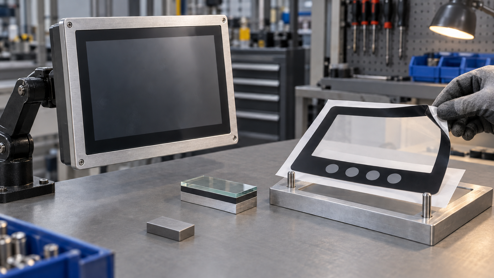
Do not send an industrial panel-PC front to a graphic-overlay supplier until the service item is classified. A separate printed PET or PC film can be quoted when it lifts from the enclosure independently and has its own outline, window, adhesive land and registration datums. A rigid cover lens, projected-capacitive touch sensor, optically bonded display or sealed front module belongs in a different supplier scope. Ask for a side-section drawing, removal evidence and one controlled sample before pricing. Then approve the film, mounted front and powered HMI in separate stages. This prevents an accurate artwork copy from becoming the wrong replacement part.
A current panel-PC launch makes front-stack ownership timely
On September 7, 2026, Senke announced a new industrial panel PC series for factory automation. The release describes machine HMI and quality-station applications, multiple screen sizes, full-lamination multi-touch and protected front assemblies. Those are the manufacturer's product claims, not universal specifications for every industrial panel PC.
The useful sourcing signal is narrower. Industrial equipment teams are integrating complete touch fronts into machines while also maintaining older installed units. When a front becomes scratched, chemically damaged, delaminated or obsolete, purchasing may ask a graphic-overlay supplier to copy the visible artwork. That request is correct only if the visible part is actually a replaceable film overlay.
The source does not prescribe a separate overlay, report a front-panel failure, name Baoshengda or establish a supplier relationship. Its full-lamination language is relevant because it reminds buyers that several visually similar fronts can have very different construction and commercial ownership.
Identify the physical item before assigning supplier scope
A graphic overlay is normally a thin printed polymer film. It may include a clear or tinted display window, printed border, surface texture, adhesive pattern and nonfunctional or tactile zones. If it is a standalone part, a controlled technician can usually remove the film while the display and touch sensor remain installed. The film bends, and its adhesive or release liner is part of the overlay drawing.
A cover lens is different. It is usually a rigid transparent plate that protects the display or touch sensor. It may carry a printed mask, which can make it look like a thick graphic overlay from the front. If the printed border is on the lens and the lens is bonded to the touch sensor, the service item may be a lens-touch subassembly rather than a film.
A projected-capacitive sensor can also be separate or bonded into the stack. Optical bonding may join the cover lens, sensor and display with no serviceable air gap. A sealed industrial front may add a gasket, metal carrier, controller board and enclosure interface. In that case, an artwork file identifies only the visible pattern. It does not define the item that should be manufactured or replaced.
Use a plain side-section sketch to name every layer from the operator side to the display. Record which layer can be removed, which supplier owns it and which surfaces are bonded permanently. If the team cannot produce that evidence, classify the RFQ as unresolved rather than guessing from a front photograph.
Compare the evidence before requesting a replacement quote
| Evidence available | What it can establish | What it cannot establish by itself | Buyer action |
|---|---|---|---|
| Front artwork or PDF | Legends, printed border, colors, nominal window and visual revision | Film thickness, lens material, touch sensor, adhesive, bonding or service boundary | Use it as print evidence, not the stack definition |
| Removed flexible film | Separate-overlay construction, real outline, window, finish and possible adhesive pattern | Original housing flatness, display active area, powered touch performance or remaining stack condition | Measure and retain it as the overlay reference sample |
| Rigid removed front | Lens outline, mask and edge treatment | Whether the touch sensor or display was originally bonded to it and should remain attached | Obtain a side-section and removal record before splitting scope |
| Enclosure and display drawings | Bezel opening, support, active area and mechanical datums | Actual print color, texture, adhesive wet-out or assembly damage | Build the controlled window and perimeter dimensions from these datums |
| Mounted unpowered sample | Edge seating, window registration, glare and visible gaps | Touch mapping, display output, firmware state, optical quality under operation or electrical safety | Approve physical fit separately from powered behavior |
| Powered complete HMI | Display visibility, touch response and system behavior under the equipment maker's method | Film material identity or supplier process capability without component records | Keep system acceptance with the HMI owner and integrator |
This evidence table stops a common transfer error. A supplier may reproduce the visible black border perfectly while delivering the wrong thickness, the wrong removable boundary or a film that masks the display active area after mounting. Appearance alone cannot resolve the stack.
Inspect removal evidence without sacrificing the master part
Start with an intact installed unit and a known revision. Photograph the front straight on, from the side and at each edge. Use a scale only in the private engineering record, not as a substitute for a controlled drawing. Record whether the surface flexes, whether a film edge is visible and whether the border continues onto a rigid lens.
If a failed or spare unit can be disassembled safely, document the order of removal. Note whether heat, solvent, tools or unusual force were required and which party approved the method. A thin film that peels from a metal bezel is useful evidence for overlay scope. A rigid front that brings the touch sensor or display with it is evidence that the service boundary may sit deeper in the assembly.
Do not destroy the only approved master sample. Keep one intact reference and use a separate sacrificial or failed unit for layer identification. Mark the revision, equipment variant and origin of each sample in the private quality record. If different models look alike, compare their side sections before combining them into one replacement family.
Contamination from removal can distort the evidence. Residual adhesive changes thickness measurements. Solvent can haze a window or attack a printed border. A cracked rigid lens may appear flexible only because it is damaged. Record the condition before and after removal, then decide which characteristics remain trustworthy for quotation.
Freeze the overlay-specific drawing only after classification
Once a separate film overlay is confirmed, release a part drawing that belongs to that film. Define the finished outside outline, every corner radius, display window, printed mask, cutout and alignment datum. Tie the window to the enclosure opening and display active area rather than to an unverified screenshot or old artwork border.
Specify the substrate, thickness, surface texture, reverse-print construction, color references and acceptable visual standard. State whether the window is clear, tinted, anti-glare, dead-front or selectively textured. The overlay supplier can review these component requirements, but the equipment owner must define the optical result needed with the actual display.
Give the adhesive its own die line. Show the continuous land around the outside perimeter and window, any keepouts, vent paths and lift tabs. Identify the housing material, coating, texture, cleaning method and assembly pressure. An adhesive coupon on a flat plate does not prove long-term bonding to a textured cast bezel or a surface contaminated during field service.
If the film includes tactile circles, embossing or membrane-switch functions, add the active-zone datums, support behind each key, circuit boundary, tail exit and connector evidence. Do not silently convert a decorative film quote into a functional keypad assembly. The supplier scope and acceptance method must change with the structure.
Approve the replacement in three separate stages
First approve the loose film. Check outline, window, border, finish, print, adhesive die line and any tactile features against the released overlay drawing. Compare it with the retained reference without treating the old part as an infallible master. Age, cleaning and UV exposure can shift color or gloss.
Next approve the mounted front. Apply the film to a production-intent bezel or a controlled service fixture. Inspect every edge, window alignment, adhesive contact, bubbles, trapped particles and the transition to the rigid glass or display. If the overlay includes keys, check them with the actual rear support and mounting pressure.
Finally approve the powered HMI under the equipment owner's method. Verify the visible display area, touch mapping, viewing angle, cleaning behavior, software states and any safety-related response at system level. A graphic-overlay supplier should not sign for the touch controller, display, optical bond, enclosure sealing, firmware or machine function.
Keep the three approvals separate even when one team witnesses all of them. A loose film can pass while the mounted window is offset. A mounted overlay can fit while the touch map is wrong. A working touchscreen can still use the wrong print revision. Separate records reveal which supplier or drawing needs correction.
Supplier boundary and RFQ checklist
A graphic-overlay manufacturer can review and quote a confirmed film part, including its print, window, surface, adhesive, embossing and controlled dimensions. Baoshengda can discuss a custom graphic overlay and film panel for a separately defined industrial front when the buyer provides enough evidence to keep the film scope distinct from the rigid touch and display assembly.
The overlay supplier does not determine whether a cover lens, touch sensor or display should be separated; validate optical bonding; repair touch electronics; certify the panel PC; or prove software, machine safety, electrical safety, ingress protection, electromagnetic compatibility or complete-system performance. Those decisions remain with the panel-PC owner, equipment manufacturer and qualified integration partners.
Prepare this drawing, sample and RFQ package:
- equipment model, variant, current supplier boundary and required service item;
- intact front photographs plus a controlled side-section drawing or removal record;
- existing artwork, governing revision and one retained physical reference sample;
- film outline, corner, cutout, window and enclosure/display datum drawings;
- display active area, printed mask, viewing direction and optical responsibility;
- substrate, thickness, finish, color reference and cleaning exposure;
- adhesive die line, housing material, surface texture, assembly method and edge condition;
- tactile, embossing, circuit, tail and connector details if the part is functional;
- loose-film, mounted-front and powered-system sample stages with named acceptance owners;
- prototype quantity, spare demand, expected production quantity, destination and required timing.
Send the available evidence through Request a Quote. The first useful response should confirm what item is actually in scope and what evidence is still missing, not promise a copied front from appearance alone.
Need help reviewing a structure?
Send your drawing, photos, application, and quantity. Baoshengda can help check the structure before sampling.
Send Drawing for Quote