
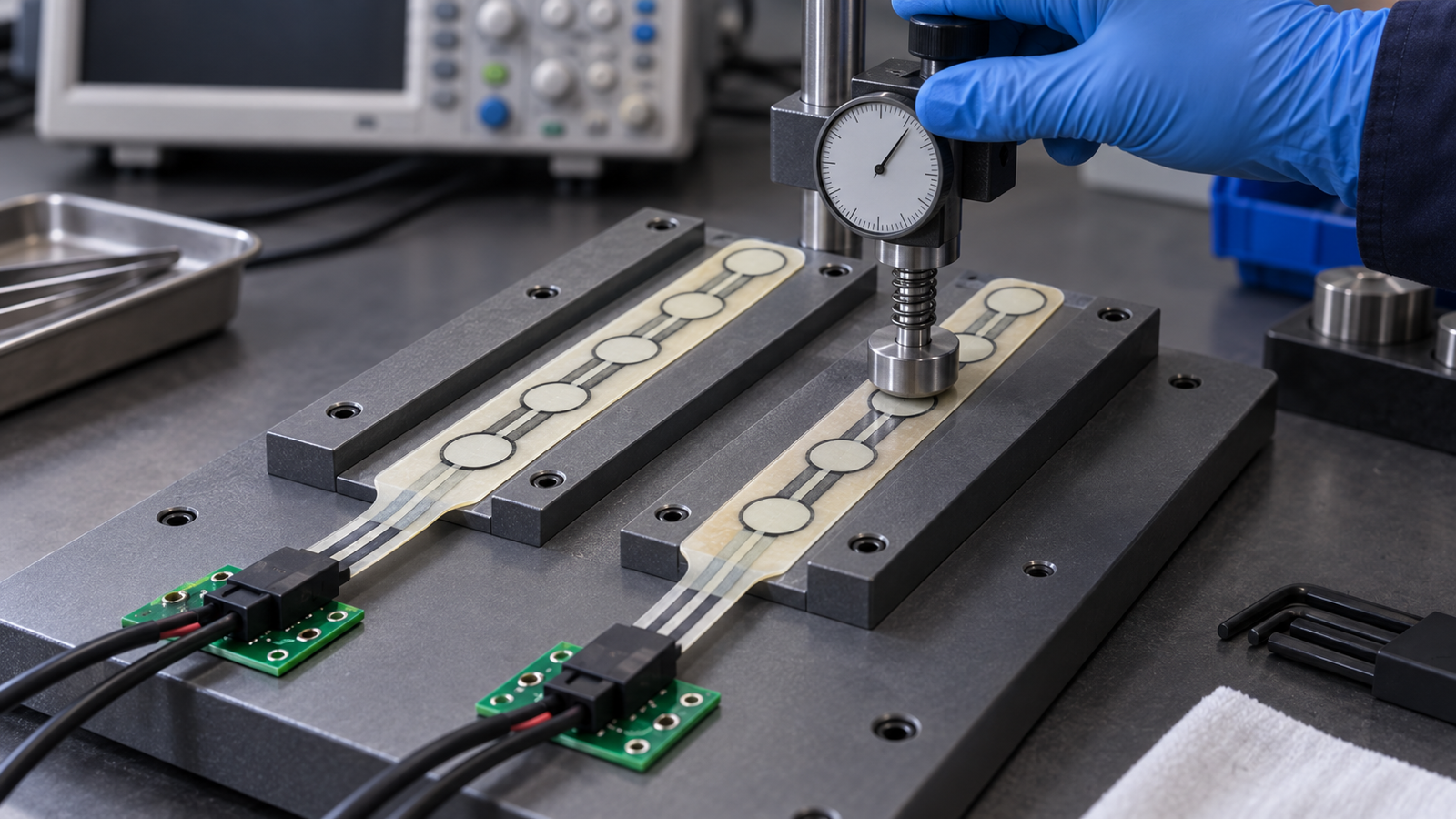
Approve a replacement FSR across a controlled loading and unloading sequence, not at one nominal resistance point. Keep the fixture, actuator area, loading rate, dwell, measurement circuit and mounted stack fixed. Compare the zero-load baseline, agreed loading points, corresponding release points, recovery time and repeatability with the approved part. Also verify active-zone geometry, tail transition, conductor and contact construction, and connector orientation. A single resistance reading can be one acceptance point, but it cannot show hysteresis, slow recovery, preload sensitivity or a fixture mismatch. Use a signed transfer matrix so the buyer, approved-part record and replacement sample are evaluated under the same conditions.
One current inspection launch exposes the transfer gap
A September 7 Fujifilm pressure-inspection system announcement separates pressure at one maximum point from pressure changes across the full pressurization process. The company describes combining static and dynamic pressure information for manufacturing inspection. Its release discusses a different measurement system, not a custom FSR, and it does not identify a Baoshengda component or supply relationship.
The useful sourcing lesson is narrower. A snapshot can hide what happens before and after the chosen point. During an FSR supplier transfer, two samples may produce similar resistance under one applied load while following different paths on the way up, on the way down or after the load is removed. That difference can change a controller threshold or create a slow return to the unloaded state even when the purchase specification lists only one nominal value.
Treat the approved part as evidence, not as an undocumented standard. Recover the released drawing, circuit condition, fixture, test method and acceptance record. If any of those items are missing, record the gap before asking a new supplier to reproduce it.
Lock the fixture before comparing materials
An FSR responds to the whole load path. A hard, small actuator concentrates stress differently from a compliant or larger puck. A soft cover, adhesive layer, housing rib, foam spacer or curved mounting surface can spread the same nominal force over another area. Preload from the enclosure may move the zero-load baseline before the first test point is applied.
Freeze these conditions for the transfer comparison:
- actuator shape, contact diameter, hardness and alignment to the active zone;
- support plate, cover layer, adhesive, spacer and any intended preload;
- loading and unloading rate, dwell time at each point and recovery interval;
- temperature and conditioning time when they matter to the buyer's application;
- measurement voltage, divider resistance, sampling interval and contact method;
- sample orientation, tail restraint and connector mating condition.
Photographs can help identify the setup, but the controlled fixture drawing and written sequence are the governing evidence. If the approved part was qualified loose on a bench but the replacement will be judged after mounting, run both conditions and do not merge the results.
Use a transfer table for loading, release and recovery
The acceptance table should describe what to measure, not invent universal values. Set the actual bands from the approved design record, controller needs and buyer-owned system limits.
| Transfer check | Controlled condition | Compare between approved and replacement samples | Decision if results diverge |
|---|---|---|---|
| Zero-load baseline | Defined rest time in the fixed fixture before contact | Initial resistance or circuit output and unit-to-unit spread | Check preload, contamination, tail strain and measurement circuit before judging the sensor film |
| Loading points | Same actuator, rate, dwell and ordered force steps | Response band at each agreed point and curve shape between points | Separate a local point shift from a full sensitivity or contact-area change |
| Unloading points | Reverse the same sequence without moving the sample | Release-side response and difference from the corresponding loading point | Review hysteresis allowance, dwell and mechanical stack rather than accepting the load-side reading alone |
| Recovery after release | Remove the defined load and measure at agreed intervals | Time to return within the buyer-defined unloaded band | Investigate residual preload, adhesive or layer compression, material recovery and circuit settling |
| Repeat cycles | Repeat the complete sequence for the agreed count | Within-sample repeatability and drift across cycles | Do not hide a cycle trend inside an average; retain the individual traces or point records |
| Mounted confirmation | Install both parts in representative buyer hardware | Threshold behavior, zone alignment, tail clearance and connector stability | Send system-level calibration or logic questions to the device owner, not the film supplier alone |
This matrix prevents an easy but misleading result: one replacement sample hits the nominal point once and receives approval while its release path or recovery remains unknown. It also prevents the opposite mistake of rejecting a component because two laboratories used different pucks, dwell times or circuits.
Decide what the component supplier can match
A custom FSR pressure sensor supplier can work from a released component drawing and an agreed sample method. The component scope can include outline, active zones, printed conductors, spacer or adhesive construction, flexible tail, exposed contacts, stiffener, connector option, continuity and buyer-defined electrical bands under the specified fixture.
The component supplier cannot derive finished-device force accuracy from one resistance value. The enclosure stack, actuator, analog front end, firmware filtering, thresholds and calibration curve remain part of the buyer's system. A film sample that meets the component matrix does not prove a medical, automotive, industrial or robotic safety function. It also does not validate overload protection, alarm logic, functional safety or regulatory compliance.
Write this boundary into the transfer plan. It keeps quotations comparable and stops system-owned work from being assumed inside a part price.
Investigate a curve mismatch without hiding it
When the replacement differs, change one variable at a time. Start by rerunning the approved and replacement parts in the same session with the same fixture and circuit. Swap fixture positions to check alignment. Inspect whether the puck reaches the same sensing zone and whether a rail or fastener adds local preload. Then check the tail for bending or pulling near the active area and confirm connector contact-side orientation.
If the mismatch remains, compare the construction inputs that were actually released: active-area dimensions, spacer opening, printed contact pattern, total thickness, cover and adhesive stack, tail transition and termination. Do not ask a supplier to copy an unknown material formula from a photograph. Define the output behavior and controlled construction that the project needs, then approve samples against that definition.
Averages can conceal the failure. Keep each unit's loading and unloading results, its recovery record and any outlier disposition. A supplier-quality engineer should be able to trace a pass decision to a sample ID and test condition without relying on an email statement that the parts were “similar.”
Send a drawing, sample and RFQ package that can be repeated
For a replacement-supplier quotation or sample request, send:
- approved-part sample status and which sample is the comparison reference;
- dimensioned outline, active-zone centers and usable contact areas;
- tail width, length, bend keepout, contact side, pitch, stiffener and connector definition;
- layer or stack requirements that the supplier is allowed to control;
- fixture drawing, actuator geometry, support surface and mounted or loose condition;
- ordered loading and unloading points, rate, dwell, rest and recovery timing;
- measurement circuit, supply condition, sampling method and data format;
- acceptance bands for baseline, loading, release, recovery and repeatability;
- appearance, continuity, packaging and traceability requirements;
- prototype quantity, production forecast and owners for component and system approval.
If an old record is incomplete, mark the missing fields and use a controlled characterization build before freezing production acceptance. Do not convert an undocumented legacy condition into a promise that every new supplier must guess.
Approve the handoff record, not three loose samples
A useful supplier-transfer approval contains the released drawing revision, fixture revision, test sequence, approved reference data, replacement-sample data, deviations and named acceptance owners. Retain the curve or point history needed to show loading, release and recovery, not only the single value used in the original purchase description.
The final decision should answer three separate questions. Does the replacement FSR match the agreed component construction? Does it meet the buyer-defined electrical bands under the controlled method? Does the finished device behave correctly after its own calibration and system verification? A yes to the first two does not automatically answer the third.
To prepare a comparable transfer package, request a quote with the released sensor drawing, fixture and stack definition, load-release sequence, circuit condition, acceptance matrix, quantities and the known gaps in the legacy record. That gives the supplier a reproducible target and gives the buyer evidence that can survive the next revision.
Need help reviewing a structure?
Send your drawing, photos, application, and quantity. Baoshengda can help check the structure before sampling.
Send Drawing for Quote