
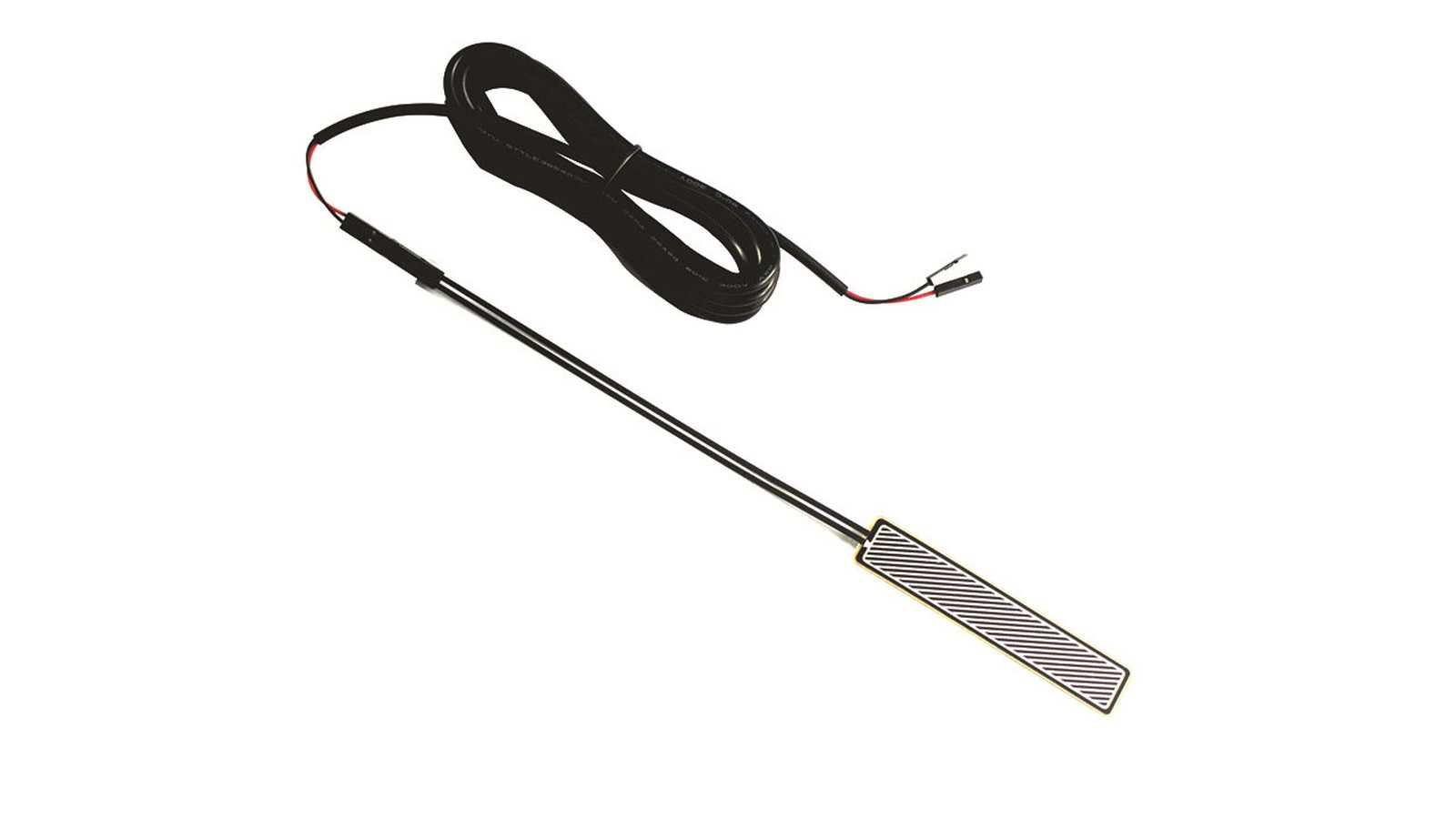
Home-monitoring and rehabilitation devices need an FSR contact design when the product must detect a touch, press, sitting point, grip action or support position without adding a large mechanical load cell. The first sourcing question is not only sensor size. The buyer should define the contact surface, the actuator shape, the expected threshold, the cover stack and the cable route before asking for a sample.
The current medical-device market is adding more sensor-based digital health technology. The FDA maintains a public page for medical devices that incorporate sensor-based digital health technology, including wearable products and non-clinical settings such as the home. That source does not make an FSR film a finished medical device. It does show why more product teams are turning body contact, pressure events and user interaction into measurable design inputs.
For a custom component RFQ, keep the discussion at component level. Baoshengda's FSR pressure sensor work can support flexible sensor films, printed traces, contact pads, tail routing and connector choices. The useful decision is how the user's force reaches the sensing area and what signal the device team expects to read from the first sample.
Start with the contact event, not the sensor outline
An FSR is most useful when the contact event can be described in plain physical terms. A rehabilitation handle may need to know whether the user gripped the pad. A home-monitoring mat may need a threshold for presence or posture change. A wearable support may need a small area that responds to strap pressure without turning every movement into a false trigger.
Write the event before drawing the film:
- What touches the sensor: finger, palm, heel, elbow, strap, cushion, foam pad or plastic actuator?
- Is the signal a simple on or off threshold, a relative pressure trend, or a rough force estimate?
- How large is the contact patch when the user applies normal force?
- Is the sensor loaded directly, through fabric, through foam or through a molded plastic part?
- Will the user press once, hold pressure for minutes, or repeat the action many times?
This step prevents a common mistake: ordering a neat sensor shape that does not match the real contact patch. If the actuator is too small, the reading may spike. If the foam spreads force too widely, the response may look weak or slow.
Choose pad size and actuator geometry together
The sensing area and the mechanical actuator should be selected as one pair. A small circular pad can work for a defined button or grip point. A longer strip can work under a support edge, cushion channel or contact rail. A wider pad may help when the user's position varies, but it can also reduce signal separation between nearby zones.
For sample drawings, mark both the electrical sensor geometry and the part that pushes on it. Include the actuator diameter, contact edge radius, foam thickness, cover film, adhesive stack and the expected direction of force. If the device has a soft cover, send the cover material and thickness instead of only sending the printed circuit outline.
One tradeoff should be discussed early. A larger pad is more forgiving when users land slightly off center, but it may hide small differences between contact points. A smaller pad can make threshold sensing sharper, but it is less tolerant of assembly shift, foam creep and user variation.
Keep the tail and connector out of the bend risk zone
Home-use and rehabilitation devices often put sensors inside curved covers, handles, straps, pads or removable cushions. The sensing film may be flexible, but the tail exit and connector still need mechanical protection. A good sample can fail later if the tail leaves the active area through a sharp bend, rubs against a plastic rib, or is pulled each time the cushion is removed.
Review these routing details before the first quotation:
- tail exit side and available bend radius inside the housing;
- connector type, pitch, locking style and assembly direction;
- stiffener side and whether the cable must face up or down;
- strain relief, tape, slot or clamp location after installation;
- cleaning, sweat, humidity or wipe-down exposure around the exit point;
- service access if the sensor or cable may be replaced.
The sensor drawing should therefore show more than the active pad. It should show the keep-out area, the tail path and the connector envelope. This is especially important when the sensor is hidden under a textile or soft pad and cannot be adjusted after assembly.
Define what the first sample must prove
An FSR sample for a home-monitoring device should not be judged only by whether it fits the outline. The buyer should define a small test plan that matches the intended contact event. For example, check the response with the real foam thickness, the planned actuator, the expected user force and the installed cable path.
Useful sample evidence includes:
- resistance or voltage trend at the intended light, normal and high contact levels;
- repeatability after several press and release cycles;
- signal drift during a held load if the device reads sustained contact;
- effect of cover film, fabric, foam or housing tolerance;
- tail movement during installation and service removal;
- connector fit against the actual PCB or cable harness.
The limitation is simple: an FSR is a practical pressure-sensitive component, not a calibrated scale by itself. If the device needs certified force measurement, the system team must define calibration, electronics, software logic and validation outside the sensor film. For many user-contact applications, the better target is a stable threshold or relative trend that the device can interpret consistently.
What to send for an FSR contact-sensor RFQ
Send a package that connects the contact event, the mechanical stack and the electrical readout. Include the sensor outline, active sensing area, tail length, connector target, available thickness, cover material, actuator shape, working temperature, humidity or cleaning exposure, expected force range, sample quantity and annual estimate. If the project is still early, send photos or sketches of the handle, pad, mat or wearable support area where the sensor will sit.
Baoshengda can review the FSR film shape, printed trace route, tail exit and connector choice against that package, then route the request through the Request Quote page. The next useful step is to build a sample that proves the real contact path, not only a film that matches a flat drawing.
Need help reviewing a structure?
Send your drawing, photos, application, and quantity. Baoshengda can help check the structure before sampling.
Send Drawing for Quote