
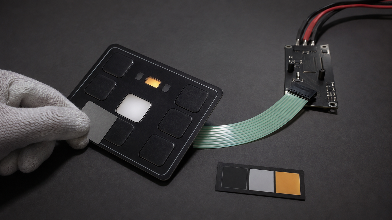
A commercial-vehicle backlit HMI should not be quoted from a request that says only ‘add RGB’ or ‘make the keys light up.’ First separate four functions: readable key legends, low-level locating light, normal status indication and any vehicle-level alert. For each illuminated zone, freeze its artwork, color, day and night state, light-block boundary, electrical input and control owner. A custom backlit membrane switch supplier can quote the printed and illuminated component only after those distinctions are visible. Vehicle warning logic, network messages, driver-information priority and finished-cab validation remain with the vehicle and controls teams.
Current cabin-lighting activity exposes a quotation gap
FORVIA HELLA announced adaptive RGB interior lighting for commercial vehicles on September 3, 2026. The release describes integrated cabin lighting that supports comfort, visual communication and safety-related functions, with applications across surfaces and information such as battery, vehicle and assistance status. It also describes lighting as a complement to displays and acoustic signals.
That announcement is useful market context, not a specification for a membrane switch and not evidence that HELLA uses Baoshengda components. It does, however, make a sourcing problem easier to see. When one illuminated surface carries key identification, position finding and status communication, a vague request for a backlit panel can hide several different optical and control responsibilities.
A panel supplier may interpret ‘status light’ as one discrete LED window. A cab electronics team may mean a network-controlled warning. An industrial designer may expect a continuous RGB effect across the face. Purchasing may compare these quotations as if they cover the same assembly. They do not. The RFQ has to convert the desired visual behavior into controlled zones, layers, circuits and acceptance conditions.
Define four light functions before choosing LEDs
Start with what the driver or service technician must perceive, not with the LED package. Give every illuminated area a stable zone ID and assign it to one of four functions.
Legend illumination: makes a printed key function readable in the specified ambient condition. The artwork, translucent ink, diffuser and light-block layers determine which parts of the legend emit light and which stay dark.
Locating light: helps a user find the control without implying that a function is active. It may use a lower brightness, a different duty cycle or a separate electrical condition from the pressed or active state.
Normal status indication: communicates a defined equipment state, such as available, active or completed. The vehicle team must define what state is represented and when the input changes. The HMI supplier can build the specified window and optical stack but cannot decide the meaning.
Alert or warning indication: may belong to a higher-level vehicle information strategy. Do not treat a color, symbol or bright LED on a membrane panel as proof of a compliant driver warning. The responsible vehicle team must control the meaning, priority, timing, diagnostics and validation.
These functions can share a physical panel, but they should not share an ambiguous requirement. If one window changes color by state, list each allowed state. If a key legend remains visible while a nearby status window changes, specify their independent brightness and light-block boundaries.
Use an optical decision table to compare quotations
| Buyer decision | Evidence required in the RFQ | Component evidence available at sample stage | Responsibility outside the panel quotation |
|---|---|---|---|
| Backlight a printed key legend | Controlled artwork, translucent and opaque regions, viewing distance, ambient condition and target state | Print registration, illuminated area, obvious hot spots, light bleed and visual comparison under the agreed fixture | Whether the selected legend and brightness support finished-cab usability |
| Add low-level locating light | Zone ID, electrical state, duty condition, intended color and relationship to adjacent legends | Zone activation, separation from adjacent windows and current under the agreed supply | When the vehicle commands locating mode |
| Add a discrete normal-status window | Window geometry, diffuser, LED color or bin, current or voltage condition and connector pin | Window position, color appearance, uniformity and unintended spill into the overlay | Meaning of the state and controller logic that drives it |
| Use one multi-state illuminated area | Complete state matrix, permitted combinations and off-state appearance | Each specified component state tested independently with the agreed driver fixture | Network signal, priority, timing, fault handling and system diagnostics |
| Treat a panel light as an alert | Controlled symbol artwork and component optical requirements only | Physical window, print, light-block and electrical response | Driver-warning hierarchy, regulatory interpretation, functional safety and vehicle-level approval |
The table prevents a low-cost single-color window from being compared with a multi-channel light guide, or a component visual sample from being presented as a vehicle-level validation result. Ask each supplier to list exactly which LEDs, resistors, light guides, diffusers, drivers, connectors and fixtures are included.
Freeze the stack that controls light bleed and uniformity
Backlighting is a stack decision. The visible face may include a printed graphic overlay, translucent legend areas, opaque masks, spacer layers, embossed keys, diffuser film, a light guide, dome or switch layers, a flexible circuit and adhesive. A small change in any one layer can move the light boundary or create a bright spot.
Show the complete section through each important zone. Mark the overlay thickness, surface texture, ink sequence, translucent color, blackout width, diffuser position, distance from the light source and the edge of any dome or spacer opening. If the same panel has both neutral-white legend light and amber status light, show the physical barrier that keeps the two zones separate. A note that says ‘no leakage’ is not enough without a boundary and a test condition.
Housing support also matters. A loose sample viewed on a white bench can appear brighter than the same panel installed above a dark bezel or deep cavity. A reflective internal surface can create a halo near the perimeter. Fasteners or ribs can push the stack closer to one LED. Provide the representative backing color, cavity depth, support surface and bezel opening before optical approval.
Do not promise numerical luminance or color tolerance until the measurement geometry, meter, supply condition, warm-up time and ambient light are defined. For an early quotation, a controlled visual comparison may be appropriate. For production acceptance, agree whether the result is a measured range, a golden sample, a photographic record with locked camera settings or a combination.
Connect every light state to the tail and connector
The optical drawing must connect to an electrical definition. Assign each legend group or status window to a circuit net, LED channel and connector pin. State the supply voltage range, current limit, polarity, common conductors and whether resistors or any driver circuitry belong on the flexible circuit or on the vehicle-side PCB.
Show the connector from one stated viewing direction. Record the contact side, insertion direction, mating-part ownership and pin numbering convention. A mirrored pin map can light the wrong zone while the front artwork still looks correct. If multiple colors share a common connection, show which combinations are electrically possible rather than assuming the controller will never request an invalid state.
Include the full flexible tail geometry. Mark the exit datum, usable bend region, first-bend keepout, stiffener, connector envelope and route past ribs or fasteners. A sample can pass on the bench yet fail after the tail is folded sharply behind a cab trim panel. The mounted sample must keep the connector accessible and the optical stack flat.
Approve the sample in off, day, night and state modes
Inspect the panel first with all light sources off. Opaque areas should hide internal components, translucent zones should have the intended unlit appearance, and adjacent colors should not show unwanted tint. Check print registration, key position, panel perimeter, tail, stiffener and connector before applying power.
Next, operate one optical zone at a time using the agreed supply or test fixture. Record the active channel and connector pins. View the panel from the specified normal position and at the worst relevant oblique angle. Check whether the intended legend or window remains identifiable and whether light escapes into a neighboring key, perimeter or status area.
Repeat the review in the defined daytime and nighttime ambient conditions. Do not use an overexposed phone photograph as the only evidence. Lock exposure when comparing samples, and include a neutral reference if photographs are part of the approval file. A luminance meter can add useful evidence only when distance, angle, aperture and measurement area are repeatable.
Then install the panel in the representative housing. Repeat the important states with the production bezel color, backing support, fasteners and tail route. Record optical results separately from the controller command that produced them. A component channel can operate correctly even when system logic requests the wrong state, and correct software cannot repair optical crosstalk inside the panel.
Keep the supplier boundary explicit
Baoshengda can review and manufacture the defined graphic overlay, translucent and opaque printing, embossed or flat key zones, windows, diffuser or light-guide arrangement, membrane circuit, integrated LEDs when agreed, adhesive, flexible tail, stiffener and specified connector. Component-level samples can be checked for dimensions, appearance, key registration, circuit continuity, channel activation, connector orientation and optical behavior under the agreed fixture and ambient conditions.
Baoshengda does not define commercial-vehicle status logic, CAN or other network messages, driver-warning priority, dimming algorithms, diagnostics, functional-safety architecture, cybersecurity, homologation or finished-cab performance. It cannot infer those requirements from a color request or the name of a vehicle function. The vehicle owner must supply and approve system meanings, permitted states, operating sequences and vehicle-level tests.
The generated cover for this article is an engineering scene that illustrates a component sample review. It is not a customer installation and does not prove vehicle performance, field reliability or regulatory compliance.
Send a quotation package that removes optical ambiguity
Before using the Request Quote page, prepare one controlled package containing:
- front artwork with stable zone IDs for legends, locating light, normal status and any alert-related window;
- off, day, night and active-state matrix for every illuminated zone;
- overlay, ink, blackout, diffuser, light-guide, key and adhesive stack sections;
- approved color references and the electrical conditions under which they apply;
- LED color or bin, voltage, current, polarity, common circuits and driver ownership;
- circuit schematic, key and light net table, connector part, contact side and pin map;
- full tail outline, exit direction, bend keepout, stiffener, connector envelope and route in the housing;
- bezel opening, support surface, cavity depth, backing color and mounted section;
- loose and mounted sample quantities, golden-sample status and controlled revision;
- optical review method, ambient conditions, viewing geometry, measurement method and pass criteria;
- a responsibility matrix for component evidence, controller commands, status meaning, warnings and vehicle-level approval.
Ask the supplier to return an explicit list of included layers, light sources, circuit elements, tooling, fixtures and sample tests. Keep every unresolved system state marked open rather than asking the panel supplier to guess. A comparable quotation begins when each illuminated zone has a physical boundary, an electrical path, an acceptance condition and a named owner.
Need help reviewing a structure?
Send your drawing, photos, application, and quantity. Baoshengda can help check the structure before sampling.
Send Drawing for Quote