Overview
An FPC membrane switch combines the user-facing overlay and switch structure with a flexible printed circuit layer or tail. It is often selected when the product housing is compact, the tail route is difficult, the connector area needs better control, or the buyer wants higher reliability in the circuit section.
FPC is not automatically needed for every membrane switch. The choice should be based on routing, pitch, pin count, bend radius, assembly process, durability, and cost target.
What is an FPC membrane switch?
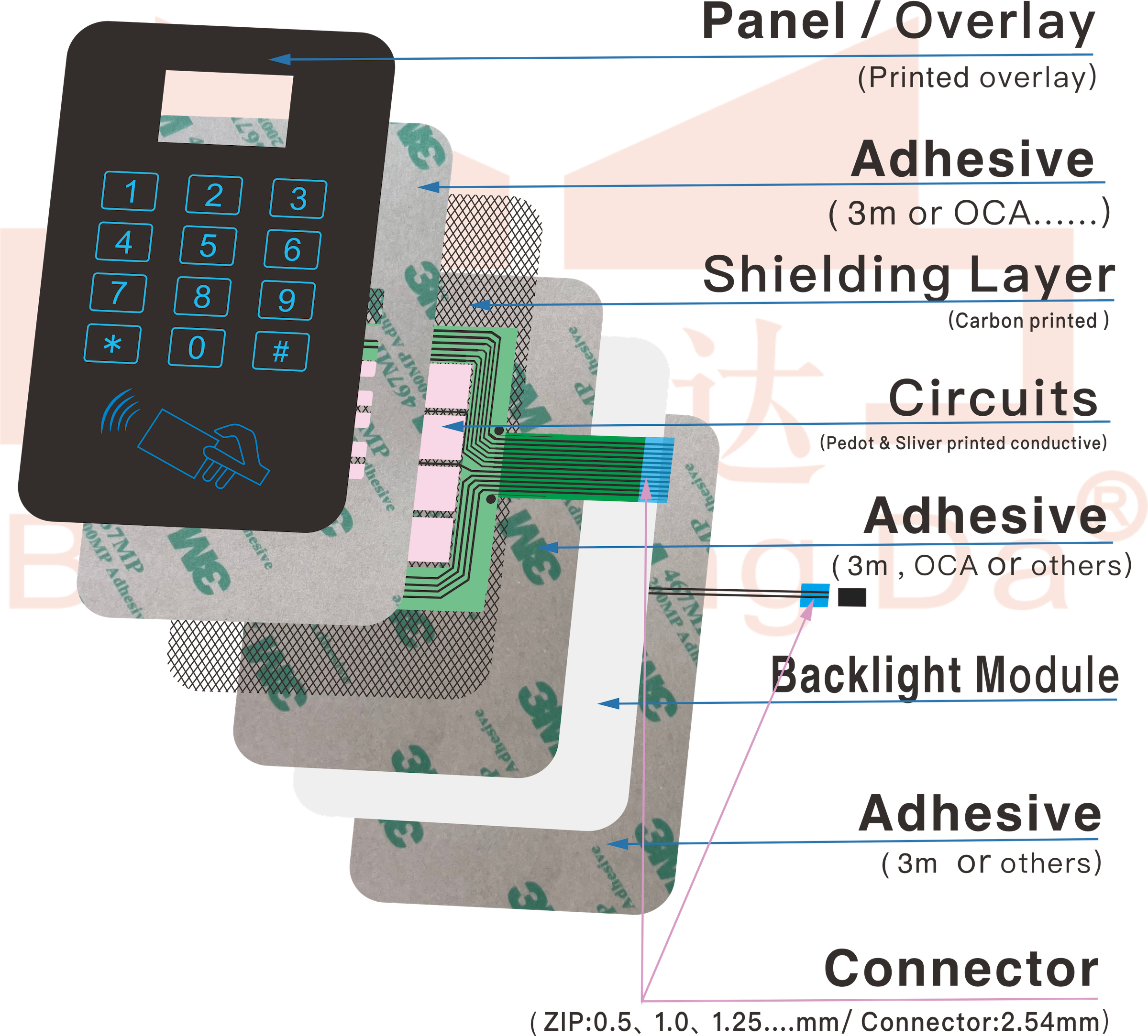
An FPC membrane switch uses a flexible printed circuit for the electrical layer or tail. The visible interface can still include PET or PC overlay, printed icons, embossed keys, LED windows, metal domes, spacer layers, adhesive, and connector options.
The FPC portion can support fine routing and stable connector mating. It is especially useful when the tail must pass through a narrow housing, fold predictably, or connect to a compact PCB.
FPC vs silver printed circuit
Silver printed circuits are widely used in standard membrane switches and can be cost-effective for many layouts. They work well when routing is not too dense and the tail route is relatively simple.
FPC circuits can be selected when the design needs tighter pitch, more robust tail handling, specific connector requirements, or better performance under bending. The tradeoff is usually higher cost and more detailed engineering review.
Connector and tail design
- Tail length, width, exit direction, and bend path should be defined from the housing, not only from artwork convenience.
- Connector pitch, pin count, contact direction, and mating connector part number should be confirmed before sampling.
- A stiffener may be needed at the connector area for stable insertion.
- LED lines, ground lines, or special functions must be included in the pin count.
- Service loop and assembly access should be considered so operators do not pull the tail during installation.
Bend radius considerations
A flexible tail can bend, but it should not be forced into a sharp fold at the housing edge. The bend radius, fold direction, reinforcement, and route should be reviewed with the enclosure. A small housing rib can create stress that is invisible in a flat drawing.
If the product will be opened for service, leave enough tail length for the cover to move without pulling the FPC. If the tail crosses metal or a sharp plastic edge, protection may be needed.
Reliability benefits
FPC can improve reliability in compact and demanding layouts by supporting controlled conductor geometry, connector-ready tails, and stable bending design. It can also reduce layout compromises when the membrane switch must connect to a dense PCB.
The benefit is strongest when the design requirement is clearly described. If the buyer simply requests FPC without explaining why, the factory should still review whether a silver printed circuit is enough or whether FPC is justified.
Applications
- Compact HMI controls where the tail must route through limited space.
- Medical, industrial, and automotive electronics with connector-sensitive designs.
- Backlit or LED membrane switches with additional electrical lines.
- Instrument panels and electronic devices requiring stable flexible connection.
- Older sample replacement where the original tail failed or the connector is difficult.
Design checklist
- Panel size, key layout, overlay material, and surface finish.
- Circuit function, pin count, connector pitch, and contact orientation.
- Tail exit location, length, bend route, and service loop.
- Housing photo or 3D file showing ribs, screw bosses, and PCB location.
- Waterproof, backlight, LED, shielding, or special reliability requirement.
- Prototype quantity, production quantity, and target lead time.
Quality control
FPC membrane switch quality checks include overlay appearance, printing alignment, die cutting, tactile feel, continuity, insulation, LED function if used, connector fit, tail stiffener position, and visual inspection of bend-risk areas.
A functional sample should be assembled into the real housing when possible. Many tail and connector risks only appear during assembly.
What to send for quotation
A clear quotation starts with ordinary project facts. If some files are not available yet, send what you have and mark the missing items as open for review.
- 2D drawing with size, outline, button positions, window areas, and tail exit.
- 3D file or housing photos if available.
- Sample photos or an old part if the project is a replacement.
- Application environment, including indoor, outdoor, cleaning, moisture, oil, or heat exposure.
- Prototype quantity and expected production quantity.
- Material requirement, surface finish, color reference, and artwork files.
- Connector requirement, tail direction, pin count, and mating board details.
- Waterproof, backlight, LED, FPC, adhesive, or special reliability requirements.
- Target lead time for samples and mass production.
Related resources
FAQ
When should I choose an FPC membrane switch?
Choose FPC when the design needs compact routing, fine pitch, reliable bending, connector-ready tails, or more demanding electrical layout than a standard silver printed circuit.
Is FPC always better than silver printed circuit?
No. Silver printed circuits are practical for many membrane switches. FPC should be selected when the project requirements justify the extra structure and cost.
What connector information do you need?
Connector part number, pitch, pin count, contact direction, mating PCB position, tail length, and tail exit direction are helpful.
Can you design the tail from an old sample?
Yes. An old sample and housing photos can help identify tail route, connector type, bend risk, and possible improvements.
Can FPC membrane switches include LEDs?
Yes. LED and backlight lines can be integrated, but the pin count, circuit routing, power, and connector arrangement must be reviewed.
What is important for bend reliability?
Bend radius, tail route, reinforcement, housing edges, service loop, and connector access are important for reliability.
Can you make prototypes?
Yes. Prototypes help verify electrical function, connector fit, tail route, tactile feel, and assembly before mass production.