
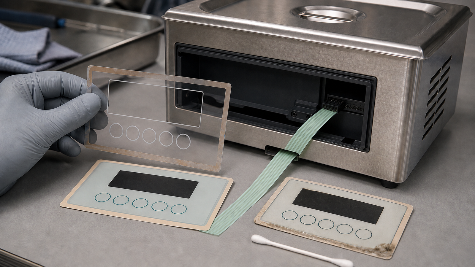
When an ultrasonic-cleaner keypad misses presses or triggers unexpectedly, do not quote a replacement from the front artwork alone. First test the same key matrix dry, then inspect the panel edge, adhesive land and tail connector for moisture paths, and finally repeat the check in the mounted enclosure with the controller state recorded. A loose panel that works dry but fails after mounting points toward support, compression, contamination or moisture coupling. The same open circuit at the tail in both dry and mounted checks points toward the switch circuit or interconnect. A supplier can rebuild the membrane assembly only after that fault boundary and the full stack are defined.
The cleaner demonstration is context, not a keypad diagnosis
A September 7 VEVOR IFA product-demonstration release includes an ultrasonic cleaner among equipment being demonstrated with multiple operating modes. That release is useful because buyers of mode-based cleaning equipment need a reliable physical input path. It does not identify the cleaner's keypad construction, report a keypad fault, name Baoshengda, or establish any supplier relationship.
The durable sourcing issue starts after a field symptom appears. A missed key can come from a worn or damaged contact, but it can also come from residue at an edge, moisture moving along an adhesive gap, excessive local support pressure, a tail bend, an incompletely seated connector, or controller logic. A ghost input can have a different cause from a stable open circuit. Replacing only the printed face without documenting the symptom can reproduce the problem and obscure the real owner.
Build a dry-versus-mounted fault matrix before requesting price
Start with the unit isolated under the equipment owner's service procedure. Record the exact key, state, frequency and operating condition. Avoid descriptions such as “sometimes bad.” Note whether the problem occurs at power-up, after a cleaning cycle, after wipe-down, only when the bezel is fastened, or after the unit cools.
Then compare a dry, supported electrical check with a mounted check. Use the connector pinout and controller input method approved by the equipment owner. Do not improvise a mains-powered test around an open cleaner.
| Observation | More likely area to investigate first | Evidence to retain before an RFQ |
|---|---|---|
| One key remains open in dry and mounted checks | Contact circuit, tail conductor or connector path | Matrix continuity by pin pair, tail inspection and connector seating result |
| Loose panel works, but the same key fails after bezel assembly | Support flatness, local compression, spacer stack or alignment | Rear support map, fastener sequence, section drawing and pressure-mark evidence |
| Symptom appears after splash, vapor or wipe-down and changes as the panel dries | Edge seal, adhesive gap, vent path, residue or connector exposure | Exposure location, cleaning agent, elapsed time, edge and rear photographs |
| Electrical continuity is stable but the controller reports the wrong or repeated state | Debounce, pull-up or pull-down, scan logic, grounding or connector mapping | Controller state log, schematic boundary and known-good input comparison |
| Several keys change together when the tail is flexed | Tail bend, stiffener, crimp, connector latch or strain relief | Bend location, mating connector, contact side, pitch and installed route |
This matrix does not prove a root cause by itself. It prevents the first quotation from silently assuming that every symptom belongs to the replaceable switch.
Inspect moisture paths and mounting pressure as one stack
A front surface can look clean while liquid or residue reaches an edge. Photograph the full front, all four panel edges, the rear adhesive land, tail exit and connector area before cleaning evidence away. Mark the orientation so the supplier can relate the suspect edge to the enclosure and gravity. State whether exposure is splash, vapor, condensation, operator wipe-down, chemical mist or an accidental spill. Also state the cleaner and disinfectant used. Material compatibility cannot be inferred from “water resistant.”
The enclosure section matters as much as the overlay drawing. Show the adhesive land width around the active area, any display window, key embossing, spacer openings, rear support, gasket, bezel lip and drainage or vent path. A narrow land, step, screw boss or unsupported pocket can create a local opening or compress the switch differently after assembly.
Use pressure-indicating film, a controlled support fixture or another method owned by the mechanical team to find high and low support regions. Do not use uncontrolled finger pressure as a release test. Record fastener torque and sequence if the bezel uses screws. A sample that passes loose on a bench has not proved the mounted stack.
Keep the tail, connector and controller inside the fault boundary
A replacement keypad is not only an artwork and contact layer. Freeze the tail exit datum, total tail length, first-bend keepout, trace side, exposed-contact length, stiffener thickness, conductor count and pitch. Identify the exact mating connector and latch direction. If the installed route folds across a sharp edge or is pulled during service, include that route in the sample review.
Continuity at exposed tail contacts is not the same as a stable signal at the controller. Retain results at both points when practical. If the switch circuit is stable but the controller input changes, the equipment owner must investigate the connector mate, cable, grounding, power, scan timing and firmware state. A membrane-switch supplier can help define and reproduce the passive circuit and mechanical interface. The supplier cannot validate the cleaner's mains isolation, ultrasonic generator, controller software, process performance or chemical safety.
For a custom membrane switch with a controlled tail and connector, the drawing should make the complete interconnect part of the controlled item rather than leaving it to a photograph or an old sample alone.
Approve three sample stages with different evidence
The first stage is a loose-panel electrical sample. Check every key and matrix path with a controlled probe or fixture, using the agreed actuation area and force method. Record released and actuated values, circuit mapping and tail continuity. This stage isolates the basic switch construction from the enclosure.
The second stage is a dry mounted sample. Install the switch with the intended adhesive, surface preparation, support land, gasket, bezel, fastener sequence, tail route and mating connector. Repeat the key and matrix checks before and after assembly. The goal is to catch stack-up or routing changes before environmental exposure.
The third stage is a controlled exposure sample owned by the equipment team. Use the actual allowed wipe-down or splash condition, followed by specified dwell and inspection intervals. The acceptance plan should say what is measured immediately, after drying and after repeated cycles. Do not convert one sample's survival into an unsupported ingress rating or chemical-life claim.
A useful release record links each result to the overlay, circuit, adhesive, spacer, tail, connector, enclosure and controller revisions. If a revision changes, identify which stage must be repeated.
What the switch supplier can decide, and what remains outside scope
The supplier can review the membrane stack, contact layout, graphic layer, window, spacer, adhesive land, embossing, tail, stiffener and connector termination. It can build samples to the released drawing and provide agreed dimensional and electrical evidence. It can also flag where the proposed geometry leaves too little sealing land or an aggressive bend near the tail exit.
The equipment owner retains responsibility for diagnosing the powered system, selecting cleaning chemicals, defining ingress and electrical-safety requirements, designing the enclosure and drainage path, and validating the complete cleaner. The controller owner retains scan logic, debounce, thresholds, grounding and fault handling. A new membrane keypad should not be represented as proof that a moisture, firmware or system-level fault has been eliminated.
Send this drawing, sample and RFQ package
Before asking for a replacement or supplier comparison, send:
- the exact failing key or matrix path, symptom state, frequency and time sequence;
- dry loose-panel continuity and dry mounted results using the same pin reference;
- full front, rear, four-edge, tail-exit and connector photographs with third-party marks removed;
- the panel outline, display window, key centers, adhesive perimeter and enclosure-section datums;
- the rear support map, gasket or bezel details, fastener sequence and allowed assembly pressure;
- exposure location, splash or vapor condition, wipe-down method, cleaning agent and dwell time;
- circuit schematic or matrix table, tail exit, bend keepout, contact side, pitch, stiffener and connector mate;
- required materials or qualification references without inventing an ingress or chemical-resistance claim;
- loose, mounted and controlled-exposure sample quantities with separate acceptance evidence;
- annual quantity, service-spare quantity, revision level, packaging needs and change-control contact.
If the fault matrix and stack are available, request a quotation with both the electrical and mechanical evidence. That gives the supplier enough information to price the intended assembly, identify assumptions and propose a sample plan without pretending the keypad owns every cleaner fault.
Need help reviewing a structure?
Send your drawing, photos, application, and quantity. Baoshengda can help check the structure before sampling.
Send Drawing for Quote