
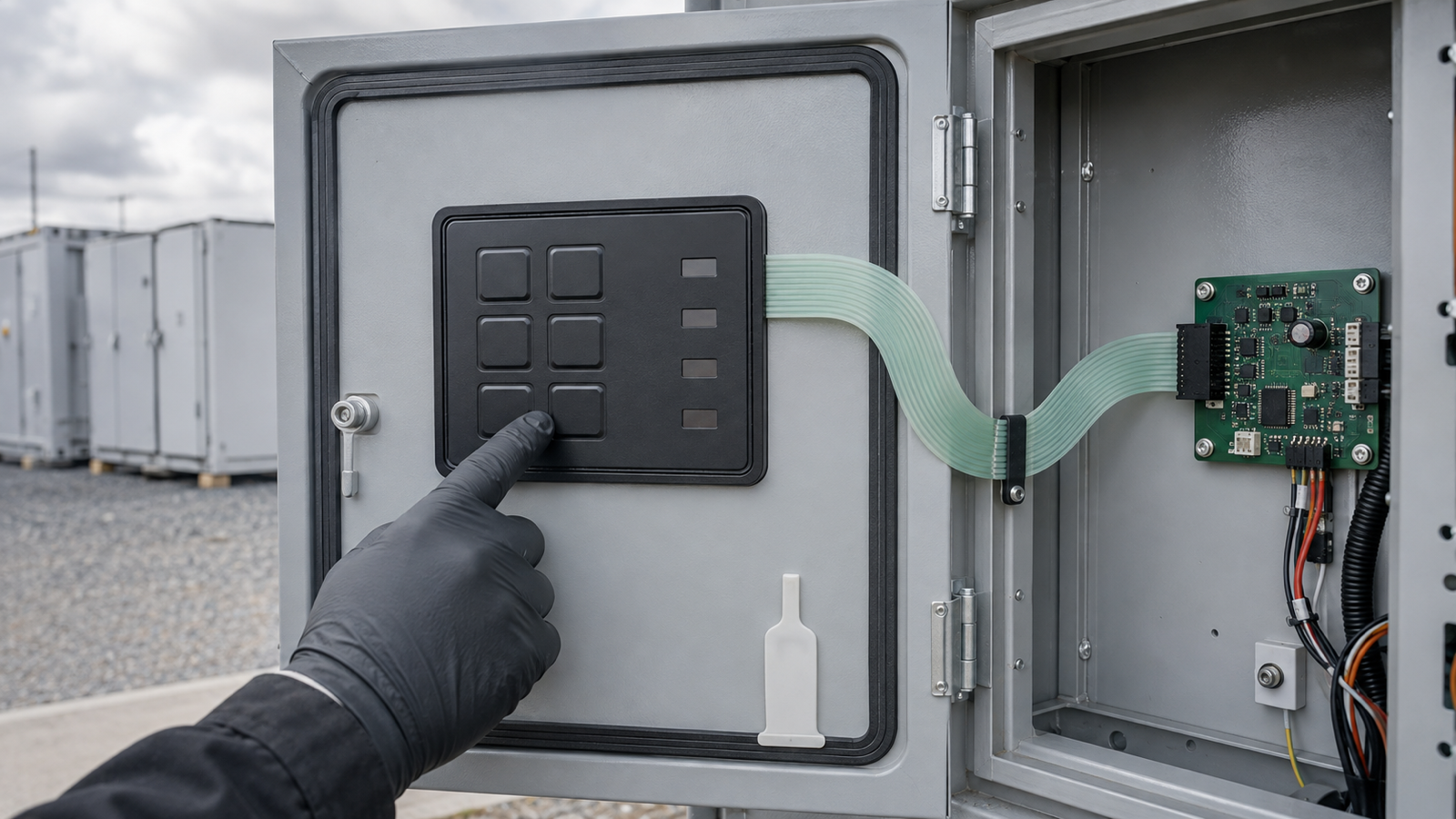
Before approving a local service-panel sample for a multi-site battery energy storage system, freeze five things: which commands remain local, which status indications must be visible at the cabinet, who owns remote-control authority, how the keypad seals to the door, and how its tail connects to the controller. A waterproof membrane switch for outdoor service controls can provide a compact physical interface, but the sample is meaningful only when it is tested in the representative door with the final gasket landing, glove condition, tail route, connector and state map. The HMI supplier does not define battery-system permissions, lockout rules or supervisory logic.
Current multi-site storage procurement makes service evidence relevant
Seven States Power Corporation announced a request for proposals for a 220 MW battery storage project on September 2, 2026. The announcement says the Energy Express Project is planned across multiple locations and that the procurement includes a 20-year long-term service agreement. It also says the assets are intended to connect to local utility distribution systems.
That announcement does not specify a membrane keypad, and it is not evidence that any party named in the RFP uses Baoshengda components. It does make one procurement question timely: how will repeatable local service actions be defined across cabinets, sites and years? A long service period magnifies small interface inconsistencies. If the same key means local reset in one cabinet and alarm acknowledge in another, or if a replacement panel has a mirrored connector, a visually similar spare may not be functionally interchangeable.
The practical response is not to copy a utility project's controls. It is to turn the buyer's own maintenance concept into a controlled local HMI package. The panel drawing, state map, enclosure section, wiring definition and sample test should agree before a supplier prices tooling or a buyer approves appearance.
Separate local maintenance controls from supervisory authority
Begin with a state and authority map. List every proposed physical key and indicator, then decide whether it belongs on the local service panel at all. A local panel may support inspection, lamp test, navigation, alarm acknowledgement or a maintenance-mode request. It should not silently acquire permission to energize, isolate, charge or discharge equipment because a convenient key was added to the artwork.
For each local input, define the permitted equipment states, required preconditions, feedback after actuation and behavior when communication is unavailable. A key can send a momentary contact to a controller, but the battery-management system or site controller must decide whether the request is accepted. The panel supplier can build the contact circuit and indicator window specified in the drawing. It cannot determine the system interlock, user role or safe operating sequence.
Treat indicator windows the same way. Give each one a stable zone ID and a single defined owner. If a lamp means only that the local controller has power, do not label it as proof that the battery string is safe. If a status is derived from the supervisory system, define what the local panel shows during network loss, controller reboot and sensor disagreement. Ambiguous green, amber and red lamps create false confidence when their meanings differ between sites.
Use one decision table for drawings, samples and responsibility
| Buyer decision | Evidence required before quotation | Evidence available from a mounted panel sample | Responsibility outside the panel supplier |
|---|---|---|---|
| Keep a command on the local panel | Key ID, requested action, permitted states, controller input and feedback state | Key position, tactile response, contact closure, circuit net and connector pin | Permission logic, interlocks, user role and equipment response |
| Show a cabinet status locally | Indicator ID, source signal, off and active states, color and viewing condition | Window position, LED activation when included, optical separation and pin mapping | Accuracy and priority of the underlying system state |
| Operate with service gloves | Glove type or thickness, actuation direction, mounted support and acceptance method | Repeatable actuation on the installed sample without edge lift or housing movement | Human-factors approval for the finished cabinet and work procedure |
| Seal the keypad to the door | Cutout, flat gasket landing, surface finish, drainage path and tail exit | Perimeter fit, gasket compression witness, edge condition and mounted leakage check | Whole-enclosure ingress rating and installation quality outside the panel boundary |
| Replace the panel during service life | Controlled revision, tail datum, contact side, connector part and pin map | Dimensional comparison, continuity, insertion fit and keyed orientation | Spare strategy, firmware compatibility and system requalification |
This table keeps three evidence levels separate. A loose component can prove appearance and circuit continuity. A mounted sample can prove fit, gasket landing, actuation and the real tail route. Only the finished equipment team can prove that a local request produces a safe system response. A supplier quotation should state which level is included instead of using one word such as tested for all three.
Freeze the mounted waterproof panel construction
A waterproof membrane switch is not waterproof by name. Its sealing performance depends on the complete path around the front face, panel edge, adhesive landing, door cutout and tail exit. Send a section drawing through the most difficult edge. Mark the front overlay, spacer and circuit outline, adhesive width, any perimeter gasket, enclosure wall, cutout clearance and nearby fasteners.
The landing surface should be continuous, flat and clean across the specified adhesive width. Paint texture, weld distortion, powder-coat buildup, recessed hardware or a drainage groove can interrupt contact. If the door has a separate compression gasket, identify whether it seals the entire door while the membrane assembly relies on pressure-sensitive adhesive, or whether a dedicated gasket surrounds the keypad. Do not combine those two boundaries in a single unspecified ingress claim.
Plan the tail exit before tooling. Show the tail centerline from the keypad datum to the first allowed bend, the minimum bend region used by the buyer, the stiffener if present, the contact side and the mating connector. Keep the first bend away from the adhesive edge and from any sharp sheet-metal cutout. A broad loop may fit in an open prototype but rub a hinge, wiring duct or door seal after the cabinet closes.
Provide strain relief that controls service movement without pinching the conductors. The connector should remain accessible for replacement yet protected from door motion. Record the insertion direction and the view used for pin numbering. A panel can pass every front-face check and still fail installation if the flex is twisted or the pin map is mirrored.
Approve loose, mounted and service-condition samples in stages
Start with a loose sample review. Confirm the complete outline, artwork zones, key centers, indicator windows, tail length, stiffener, exposed contacts or connector and drawing revision. Measure dimensions from the same datums used on the enclosure drawing. Check every key circuit and every specified indicator channel before adhesive is exposed.
Next, install the sample in a representative production door or a controlled door coupon. Use the specified coating, surface preparation, cutout, mounting pressure and dwell time. Inspect the full perimeter for trapped debris, incomplete contact, edge lift and local distortion. Route the tail through the production opening, apply the planned strain relief and close the door through its full travel without pulling the connector.
Then repeat the functional checks with the service glove and access posture named in the requirement. Actuate each key several times without bracing the overlay edge. Verify that the controller receives only the intended input and that adjacent keys do not register. Activate each indicator independently with the agreed fixture or controller state. Record the connector pins, supply condition and observed zone so a later spare can be compared.
Environmental evidence should match the declared boundary. A controlled water-path check can look for edge entry around the panel and tail exit, but it does not establish the enclosure's final IP rating. Temperature exposure should use the buyer's real material stack, door coating and adhesive dwell. After conditioning, recheck adhesion, key response, circuit continuity, tail condition and connector retention. Do not approve the sample from a dry bench photograph when the actual decision is a mounted outdoor-service interface.
Keep the supplier boundary explicit
Baoshengda can review and manufacture the specified graphic overlay, printed key and indicator zones, embossed or flat keys, membrane circuit, integrated LEDs when agreed, adhesive, gasket interface, flexible tail, stiffener and specified connector. Component and mounted-sample checks can cover dimensions, appearance, key registration, circuit continuity, connector orientation, actuation under an agreed setup, indicator activation and visible panel-edge condition.
Baoshengda does not define the battery-management system, site controller, SCADA architecture, charging or discharging authority, lockout and tagout procedure, emergency isolation, electrical protection, cybersecurity, firmware compatibility, alarm priority, utility interconnection or whole-cabinet ingress rating. Those requirements must come from the equipment owner and system integrator. The source article's RFP scale and service term are market context only, not a component specification or customer relationship.
The generated cover is an engineering application scene. It illustrates a mounted keypad, gasket, flex tail, connector and glove-actuation review. It is not a customer site, factory photograph, live energized service procedure or proof of BESS performance.
Send an RFQ package that can support sample approval
Before using the Request Quote page, prepare one controlled package with:
- front artwork with stable IDs for every physical key and indicator window;
- a local command and status matrix showing system state, permitted action, feedback and offline behavior;
- a responsibility table separating membrane-panel evidence from controller, BMS, SCADA and finished-equipment validation;
- door and panel drawings with shared datums, cutout, coating, surface finish and mounting orientation;
- layer stack, overlay surface, adhesive or gasket material request and required landing width;
- perimeter, drainage and tail-exit sections without vague waterproof labels;
- full tail outline, first-bend keepout, service loop, stiffener, strain relief and closed-door clearance;
- connector manufacturer and part, contact side, mating part, insertion direction and pin map;
- electrical schematic for keys and LEDs, including supply, polarity, current limit and driver ownership;
- glove condition, actuation method, viewing distance and ambient-light condition;
- loose, door-coupon and representative-cabinet sample quantities with controlled revisions;
- dimensional, continuity, mounted-fit, actuation, indicator, conditioning and reinspection criteria;
- spare and change-control rules for artwork, materials, circuit, tail, connector and firmware interface.
Ask each supplier to return assumptions and open points with the quotation. A comparable sample plan exists only when the same drawing identifies what the technician can touch, what the controller decides, how the interface is sealed and how the complete tail and connector fit the cabinet. That package gives purchasing, mechanical, controls and service teams one evidence chain instead of four different interpretations of a local panel.
Need help reviewing a structure?
Send your drawing, photos, application, and quantity. Baoshengda can help check the structure before sampling.
Send Drawing for Quote