
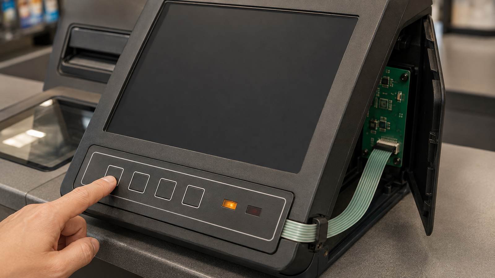
For a POS register that changes between staffed and self-service modes, do not choose touch-only, physical-key or hybrid controls by counting functions. First freeze which input owns each action in every operating, transition and recovery state. Keep context-changing customer choices on the screen. Reserve a dedicated physical key for an action only when tactile location, immediate access or operation during a blank or blocked screen is genuinely required. Use a hybrid layout only when duplicate actions have explicit priority and feedback. Approve the loose membrane keypad, mounted terminal and scripted mode handoffs separately before releasing artwork or tooling.
Current POS and board-to-flex updates expose one connected HMI decision
A September 3 FamilyMart announcement about its new POS rollout says the register can change between staffed and self-service operation. On the same date, Panasonic published a CF3 board-to-FPC connector new-release notice. Neither source describes a Baoshengda membrane switch, proves a particular POS keypad construction or identifies Baoshengda as a supplier. The connector notice also does not establish that the cited POS system uses that connector.
Together, the updates expose a practical buyer boundary. A checkout terminal is no longer one fixed screen with one fixed operator, while every physical key or indicator still has to reach a controlled PCB input through a defined tail and connector. A customer, a cashier and a service technician may meet the same enclosure under different permissions. A touch action that makes sense in staffed operation may be hidden in self-service mode. A physical key that is always electrically active may create a duplicate command when the screen presents the same action. A recovery key that is clear to trained staff may confuse a customer if its artwork remains visible.
Control allocation therefore needs a state model before it needs a key count, and the resulting circuit needs a connector definition before sample approval. This is a buyer decision because it changes the overlay, circuit, indicator windows, tail conductors, contact orientation, connector pins, enclosure support and acceptance plan.
Write the action-state map before drawing the front panel
Begin with actions, not components. List every action that can reach the front interface: start, confirm, cancel, back, staff call, receipt feed, accessibility assistance, operator sign-in, service acknowledgement and controlled restart. Then mark who may use it and when.
Use at least these state columns:
- powered off or starting;
- staffed and ready;
- staffed during a transaction;
- self-service and ready;
- self-service during a transaction;
- staff assistance requested;
- payment or network interruption;
- controlled service mode;
- restart and return to operation.
For each cell, state whether the action is available, unavailable or available only after authorization. Also state the visible response. A disabled physical key with no feedback looks like a failed key. A touchscreen action that disappears without showing the new route looks like a software defect. A physical and touch action that remain active together can generate two input events unless the system owner defines priority and debounce behavior.
The front-panel drawing should follow this map. It should not be the document that invents it.
Compare touch-only, physical-key and hybrid allocations by failure path
The correct choice varies by action. A changing product category or payment choice normally belongs on the touchscreen because context and language can change. A high-frequency trained-operator action may benefit from a tactile key. A recovery action needs special scrutiny because a physical key can remain reachable when the display is blank, but its electrical availability still depends on the controller and power domain.
| Allocation option | Good fit | Evidence needed before approval | Common mistake |
|---|---|---|---|
| Touch-only | Contextual choices, multilingual prompts and customer flows that change by screen | Screen-state map, touch-target bounds, disabled-state feedback and recovery route | Assuming a visible touch target is available in every mode |
| Dedicated physical key | Repeated trained-staff action or a defined assistance action that benefits from tactile location | Key force, travel or snap feel, electrical output, artwork visibility, active-state feedback and mounted support | Keeping the key electrically active in a mode where its legend should not invite use |
| Hybrid, separate actions | Screen handles context while a physical key owns one fixed action | Unambiguous action ownership, spacing, controller mapping and transition script | Treating the key as a generic backup without defining when it is accepted |
| Hybrid, duplicated action | Same function can be reached on screen or key for a documented reason | Event priority, debounce, simultaneous-input behavior, audit record and user feedback | Sending two commands or logging one action twice |
| Service-only physical key | Controlled maintenance or restart action behind an access boundary | Access method, authorization owner, power-domain behavior and return-to-service test | Publishing a service function on the customer-facing artwork |
Do not claim that physical keys are always safer or more reliable. They solve a tactile-location and access problem, but they add mechanical tolerances, artwork, circuit inputs and possible state conflicts. Touch-only designs reduce front-panel parts but depend more heavily on screen availability and clear recovery behavior. A hybrid design is justified only when its added path is explicitly controlled.
Treat the handoff as a transition, not two static screens
A terminal can pass every staffed-mode test and every self-service-mode test yet still fail during the handoff. The transition may occur while a receipt is printing, a payment peripheral is reconnecting, a staff-call event is pending or a key is still pressed. Test the path between modes, not just the endpoints.
Build a short transition corridor for each mode change. Record the starting state, initiating action, key and touch availability during the change, indicator behavior, completion condition and allowed recovery. Include these cases:
1. A physical key is held while the mode changes.
2. The same action is touched and keyed within the debounce interval.
3. The display is blank during startup while the keypad controller is already powered.
4. A staff-call request is active when staffed mode resumes.
5. Network or payment service returns after a local cancel action.
6. Power is removed and restored while a key is pressed.
The membrane-switch supplier does not decide the terminal state machine, but the buyer needs the state machine to define which electrical outputs and indicator windows the component must support. A vague request for four keys and two LEDs cannot establish that boundary.
Approve the mounted interface through three evidence layers
First approve the loose membrane-switch sample electrically and mechanically. Measure each key at the agreed test point. Record circuit resistance or contact behavior, key feel or force method, indicator polarity, tail pinout and connector orientation. This confirms the component construction without pretending it proves terminal behavior. The drawing should also freeze tail contact side, stiffener length, insertion direction, mating connector part or approved equivalent and accessible rework clearance. A board-to-FPC connector announcement is not a substitute for this POS-specific interface definition.
Second test the keypad mounted in the production-intent enclosure. The rigid support, adhesive land, bezel step, fastener load and local gap can change feel and contact repeatability. Exercise the key near the center and expected edge-use positions. Check that the indicator windows remain readable under the intended viewing angle without turning the cover into a brightness claim. Cycle the access panel and verify that the tail does not rub, fold at the stiffener or pull on the connector.
Third run the scripted transition corridor on the full terminal revision. Use the final controller input map and released software build. Log the electrical input seen by the controller, the terminal state before and after the action and the user-visible response. Keep this evidence separate from payment authorization. A key event can be delivered correctly while the transaction system rejects or ignores it for valid software reasons.
A mounted sample should be rejected if the key circuit passes loose testing but the bezel causes intermittent actuation, if an inactive key has no visible disabled response, or if the tail route changes when the side cover closes. Those are distinct defects and should not share one generic pass label.
Keep the tail, connector and controller map in the same change record
A front panel is not complete when only the artwork and key positions are frozen. Include the flexible tail exit datum, first-bend keepout, conductor pitch, contact side, stiffener, connector orientation, latch access and strain relief. Show the route with the access cover both open and closed.
Tie each key and indicator to a named connector pin and controller input. If the software team renames an action, do not silently reuse an existing pin without updating the state matrix. If a replacement controller reverses active level or changes pull-up values, the component sample may still be correct while the assembled response changes.
For an OEM terminal, a custom membrane switch with defined key zones, indicator windows, tail and connector can be reviewed against the enclosure and controller map. Feasibility still depends on the actual stack, circuit, environment, artwork, mounting and acceptance method. A catalog image cannot approve the mounted route.
Separate component evidence from payment and terminal responsibility
The membrane-switch supplier can review the overlay outline, key geometry, tactile construction, printed circuit, indicator-window build, tail, contact termination, connector option and agreed sample-level electrical evidence. It can manufacture to controlled drawings and report results from an agreed component or mounted fixture.
The supplier cannot validate payment security, software permissions, transaction records, accessibility compliance, retail workflow, cybersecurity, terminal certification or the full mode state machine without the complete system requirements and responsible owners. It also cannot promise that a physical key remains available during a screen or network fault unless the terminal architecture supplies the required power, input and software path.
The terminal owner should approve control allocation and transition behavior. The payment-system owner should approve transaction and security logic. The enclosure owner should approve support, sealing and service access. Put these owners beside the sample evidence rather than burying them in a general disclaimer.
Send one control-allocation and sample package with the RFQ
A useful request should contain:
- the staffed, self-service, assistance, interruption, service and restart states;
- the action-state matrix showing which touch and physical inputs are available in each state;
- the reason each physical key exists and whether any action is duplicated on screen;
- active, inactive and transition feedback for every visible key and indicator window;
- front artwork, window and key-zone drawing with viewing and reach constraints;
- overlay stack, tactile construction, adhesive land, bezel support and enclosure section;
- circuit schematic or matrix, electrical limits, indicator polarity and controller input map;
- tail exit, bend keepout, stiffener, contact side, pitch, connector, latch access and strain relief;
- loose-component, mounted-enclosure and full-terminal transition tests with separate acceptance criteria;
- sample quantity, production quantity range, change control and failure-analysis responsibility.
Send that package through the Request Quote page. The first engineering response can then identify which actions belong on the screen, which justify a dedicated membrane key, which hybrid paths need conflict rules and what must be proven before artwork or tooling release.
Need help reviewing a structure?
Send your drawing, photos, application, and quantity. Baoshengda can help check the structure before sampling.
Send Drawing for Quote