
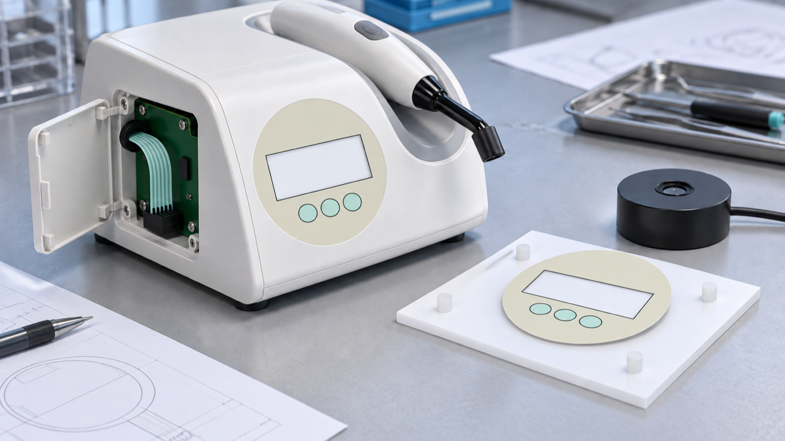
A membrane control-panel sample can approve physical fit, key position, legend readability, tactile response, circuit mapping, tail routing and connector compatibility only when it is checked in the intended housing with the intended electronics. It cannot approve radiant power, exposure-time accuracy, firmware, battery behavior, electrical safety or the finished dental device. For a quotation, split acceptance into three evidence sets: the loose interface, the mounted interface, and the complete curing-light system. Give each set a named owner and test method. That prevents a responsive keypad or clean artwork from being misread as proof that the light output and treatment-related functions are correct.
A current guidance change makes the evidence split timely
The U.S. Department of Health and Human Services lists the FDA's final guidance for dental curing-light 510(k) submissions with an issue date of September 2, 2026. The notice says the guidance covers device description, performance testing and labeling. That makes evidence ownership a current manufacturing question, not because a membrane interface establishes compliance, but because each part of a device submission needs the right supporting evidence.
The public guidance does not describe a Baoshengda component, identify a supplier, report a keypad fault or establish any commercial relationship. Dental curing-light designs also vary. Some place controls on a handpiece, while others may use a console, charging base or power module. This article addresses only designs that use a separate membrane control panel or similar thin physical interface.
The practical mistake is approving a neat panel and then treating the whole device as settled. A panel supplier can reproduce the controlled interface stack. The dental-device manufacturer still owns optical performance, software, power, safety, cleaning validation and the finished product.
Approve the control path, not the light output
Begin with a one-page evidence map. Put every acceptance item under the party that can actually demonstrate it. The interface supplier can measure the supplied panel, inspect its artwork and circuit, and build it to the released drawing. The equipment team can install it, drive its inputs and verify how the complete unit responds. Optical specialists and the device manufacturer must own output and exposure evidence.
For the control path, freeze the physical key identity before artwork release. A mode key, time key and start key must not move between the overlay drawing, circuit map and software input table. If two variants share the same outside shape but use different functions, give each a controlled artwork and circuit revision. A common envelope is useful only when variant identity cannot be mixed.
Next, define the window. A blank opening in a sample is not enough. State its visible area, border, registration datum, surface finish, display stack behind it and the allowed viewing direction. If the display conveys time, mode or condition, the device team must verify that the displayed state agrees with the physical input. The panel supplier can hold the window geometry; it cannot prove that the display or controller state is correct.
Finally, freeze the interconnect as part of the supplied item. Record the tail exit, length, first-bend keepout, conductor count, contact side, pitch, exposed-contact length, stiffener and mating connector. A correct front panel with a mirrored contact side or a tail that cannot reach after the housing closes is not an approved sample.
Three interface decisions carry most sample risk
The first decision is where the panel ends and the equipment begins. Show the adhesive land, rear support, bezel edge, screw bosses, display opening and any gasket in one section drawing. A loose panel can feel correct but change after it is bonded over an unsupported pocket or compressed near a key. Approval must state the actual mounting surface and assembly process.
The second decision is how the operator's press becomes an electrical input. Define the active key area, circuit matrix or common line, released and actuated acceptance method, connector pin reference and the controller input boundary. Do not use an informal bench press as the only tactile or electrical release record. The method must be repeatable across the agreed sample quantity.
The third decision is how variants are controlled. If exposure modes, regions or models use different legends or key assignments, maintain a model-to-artwork-to-circuit table. Packaging and labels for incoming inspection should reference the same revision. A dimensional pass does not prevent the wrong functional variant from reaching assembly.
Use an evidence table before signing the sample
| Acceptance item | The interface sample can support | Evidence that remains outside the interface sample |
|---|---|---|
| Panel outline and mounting | Outside dimensions, corner radii, window and key datums, adhesive land and flatness method | Final enclosure strength, powered electrical safety and complete cleaning validation |
| Key operation | Agreed tactile and electrical response at specified key zones, with the released circuit and connector | Firmware debounce, mode logic, exposure timing and fault handling |
| Artwork and window | Controlled legends, color reference, surface finish, window position and visible area | Display content accuracy, software state, optical emissions and clinical labeling decisions |
| Tail and connector | Exit location, conductor map, contact side, pitch, stiffener, bend keepout and mating reference | Board design, cable strain in the full device, power integrity and electromagnetic behavior |
| Mounted interface | Fit, edge seating, key accessibility and input continuity in the intended housing | Radiant power, spectral output, battery runtime, thermal behavior and finished-device performance |
This table is not a substitute for the manufacturer's design-control or regulatory process. Its purpose is narrower: it stops an interface acceptance signature from silently absorbing tests the component cannot perform.
Release samples in three distinct stages
Stage one is the loose interface. Inspect dimensions, print, window, tactile zones, circuit mapping, tail and connector. Use the released drawing and record the actual sample identity. If a keypad has three keys, check all three rather than choosing one convenient location. Retain a signed reference sample only after the drawing and measured evidence agree.
Stage two is the mounted interface. Install it on the intended enclosure surface with the production adhesive, surface preparation, support land, bezel and tail route. Close the housing using the normal sequence. Then repeat key accessibility, continuity and displayed-state checks with the equipment team's controlled electronics. This stage finds edge lift, support distortion, key interference and tail strain that a loose sample cannot reveal.
Stage three is complete-device verification, owned by the dental-device manufacturer. It includes optical output, exposure timing, software state, power, thermal behavior, cleaning, safety and all other complete-system requirements selected by the manufacturer. If an interface change could affect those requirements, the manufacturer decides what must be repeated. A component supplier should not convert a mounted keypad pass into a finished-device claim.
Use separate acceptance signatures or clearly separated sections on one report. The interface supplier signs only the agreed component evidence. The equipment team signs the mounted integration results. The responsible device organization signs the complete-device evidence.
Define the supplier boundary before quotation
A supplier of a custom medical-device HMI membrane panel can review the panel outline, display window, key zones, graphic layer, adhesive land, circuit mapping, tail, stiffener and connector termination against buyer-supplied information. It can flag missing datums, conflicting pin maps, weak tail-bend definitions and variant-control gaps. It can also build loose or mounted-interface samples when the required fixture, housing and acceptance method are available.
The interface supplier cannot establish radiant power, wavelength, exposure accuracy, treatment effectiveness, battery management, charger safety, software correctness, electrical safety, biocompatibility, cleaning compatibility or regulatory clearance for the complete curing light. Those decisions depend on the finished design, intended use and evidence controlled by the device manufacturer.
That boundary should appear in the quotation assumptions. It protects both sides from approving different products under one sample number.
Send a compact drawing, sample and RFQ package
Before requesting price or replacement samples, send:
- the panel outline, corner radii, key centers, display-window visible area and common datums;
- the intended mounting surface, adhesive land, rear support, bezel section and housing material;
- the key function table, circuit matrix, pin numbering and connector mate;
- the tail exit, length, first-bend keepout, contact side, pitch, exposed length and stiffener;
- the artwork files, color and finish references, window requirement and variant matrix;
- the intended cleaning agents and wipe method for material review, without assuming compatibility before validation;
- loose-panel and mounted-interface sample quantities with separate acceptance methods;
- the owner of optical, software, electrical-safety and complete-device evidence;
- prototype, pilot, annual and service-spare quantities with controlled revision levels;
- packaging, labeling, traceability and change-notification requirements.
When those inputs are ready, send the control-panel drawing for quotation. Ask the supplier to list assumptions and open items rather than hiding them inside a unit price. The result should be a quote for a defined interface and a sample plan that proves what the interface can actually own.
Need help reviewing a structure?
Send your drawing, photos, application, and quantity. Baoshengda can help check the structure before sampling.
Send Drawing for Quote