
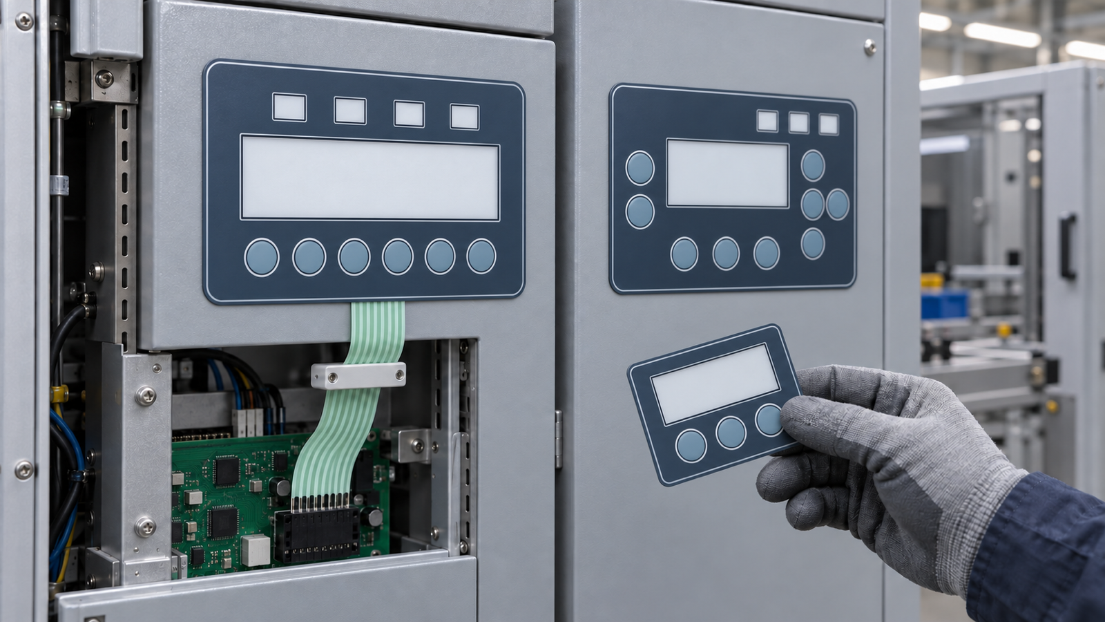
Keep the operator-facing language common, but do not force unlike machines into one electrical and mechanical keypad design. For a battery pilot line assembled from several machine builders, standardize the things an operator must recognize quickly: panel material family, contrast rules, tactile behavior, indicator conventions, window treatment and layout logic. Keep each machine's circuit matrix, exact command set, tail exit, connector, pinout, mounting envelope and controller interface under variant control. Approve a shared HMI family master, then approve one mounted electrical sample for every machine variant. This gives the line a coherent interface without hiding critical equipment differences.
The integration problem starts above the individual machine
A September 9 Siemens announcement about the Battery-NY pilot factory describes standardized automation, equipment-interface and data principles across equipment from multiple machine builders. The source identifies a real scale-up problem: specialized battery-production equipment often arrives with different control and data systems. It does not disclose the construction of local keypads, identify Baoshengda as a supplier or prescribe one physical HMI architecture.
The useful component question is therefore narrower. A mixing unit, coating machine, slitter and inspection station may belong to one pilot line, but they do not perform the same actions and may not share the same controller, enclosure or maintenance access. The integrator needs consistency where it helps the operator, and controlled differences where the machine interface requires them.
Treat the local membrane HMI as two linked layers. The first is a family language that can be recognized across the line. The second is a machine-specific interface that must match one controlled drawing and one controller input.
Make the common layer visible and tactile
A common platform should help an operator recognize that panels belong to the same equipment environment before reading every legend. Useful common rules can include:
- one approved overlay-film and surface-finish family for comparable indoor exposure;
- a consistent contrast hierarchy for normal actions, state indicators and protected service functions;
- the same tactile reference for equivalent key classes, subject to each panel's size and switch stack;
- a shared approach to display-window clarity, indicator-window diffusion and dead-front areas;
- common minimum key spacing and grouping logic for gloved or repeated operation;
- one family-level artwork rule for font, line weight, icon style and revision identification.
These are design rules, not a single universal production file. A common color or dome feel does not make two circuits interchangeable. It only gives the operator a stable visual and tactile grammar.
Keep the machine interface under variant control
The dimensions and electrical details that connect a membrane panel to a machine must remain specific to that machine unless engineering evidence proves they are identical. Forcing them into one platform can create a panel that looks correct but cannot be mounted, connected or interpreted correctly.
| Decision layer | Common across the HMI family | Machine-specific control | Evidence to approve |
|---|---|---|---|
| Surface and visual grammar | Film family, finish, contrast hierarchy, artwork rules | Exact legends and process-state wording | Family artwork master plus one printed color and finish coupon |
| Tactile behavior | Reference key class and relative grouping rules | Key count, actuation map and protected functions | Tactile reference coupon plus variant key map |
| Windows and indicators | Window treatment and indicator-style rules | Window size, viewing area, LED location and state meaning | Controlled window drawing and powered mounted sample |
| Electrical interface | Documentation format and test-record format | Circuit matrix, common line, resistance requirement, connector and pinout | Variant schematic, continuity record and mating-connector check |
| Mechanical integration | Drawing datum convention and adhesive specification method | Outline, cutouts, tail exit, keepouts, bend path and housing stack | Enclosure drawing, mounting section and fitted sample |
| Revision control | One family naming and approval process | Variant suffix, machine owner and change history | Approved family master linked to every variant drawing |
The table separates reusable decisions from interfaces that can fail silently if copied. The exact boundary should be agreed before artwork release, not discovered when a finished panel reaches the machine.
A family master is not a universal keypad drawing
Use a family master to control what must look and feel related. It can define the approved color references, surface finish, key-shape family, indicator-window style, artwork rules and identification format. It should also say which attributes are intentionally not common.
Each machine then needs a variant pack. That pack should contain its outline and cutouts, window dimensions, key and indicator map, circuit matrix, tail geometry, connector and pinout, adhesive or mounting stack, environmental assumptions and revision owner. If a machine builder changes a controller input or connector, the family master may remain unchanged while the variant drawing moves to a new revision.
This separation reduces two opposite risks. Without a family master, the line can accumulate unrelated panel styles that increase training and spare-part confusion. Without variant control, a common-looking panel can be ordered against the wrong electrical or mechanical interface.
Approve the platform at three practical levels
Start with a visual and tactile family coupon. It can compare the overlay film, finish, key embossing or dome reference, indicator-window appearance and color targets without pretending to validate a complete machine interface. The coupon answers whether the family language is suitable.
Next, approve an electrical article for each variant. Check every key position against the matrix, confirm the connector and contact side, identify the pinout revision and verify that the tail length and exit direction match the controlled drawing. A panel from another machine cannot substitute for this check merely because it shares the same colors.
Finally, approve a mounted sample on the actual enclosure or a representative production fixture. Review window alignment, adhesive or fastener support, edge clearance, tail bend path, connector seating, service access and the way operators distinguish key groups. If the display, controller or enclosure is not available, record that limitation rather than treating the loose panel as a finished-machine approval.
What the panel supplier can verify
Baoshengda can review a custom membrane switch platform and its controlled variants at the component level. The useful review scope includes overlay construction, tactile-zone layout, display and indicator windows, circuit matrix, tail exit, connector and pinout, adhesive stack, drawing datums and sample-to-drawing consistency.
The machine builder or line integrator still owns process logic, permissions, PLC or controller software, interlocks, risk controls, state meanings and validation of the complete battery-production equipment. A passed membrane-panel continuity check does not validate the machine action assigned to that input. The component drawing and the controller interface definition must meet at one controlled revision.
Prepare one platform pack and one variant pack
For a useful engineering review, separate the RFQ material into two folders or clearly labeled drawing groups.
Common platform pack:
- intended equipment family and operating environment;
- approved film, finish and color-reference method;
- tactile-key classes and grouping rules;
- display and indicator-window conventions;
- artwork and revision-identification rules;
- expected annual family volume and the list of planned variants.
Per-machine variant pack:
- machine name or neutral variant code and drawing owner;
- front-panel outline, cutouts, windows and mounting datums;
- key, indicator and process-state map;
- circuit matrix, connector, contact side and pinout;
- tail exit, length, bend route and keepout area;
- adhesive or mechanical mounting stack;
- sample quantity, inspection record and approval owner.
When these two levels are separated, a supplier can quote the shared tooling or material logic and the true variant work without assuming that similar-looking machines are electrically interchangeable. If your pilot line includes several local panels, send the family master and at least one complete variant pack for quotation.
Need help reviewing a structure?
Send your drawing, photos, application, and quantity. Baoshengda can help check the structure before sampling.
Send Drawing for Quote